
Building a Bluetooth-controlled robot with MIT App Inventor and the HC-05 module is one of the most satisfying projects you can complete in a weekend. You design your own Android app, write Arduino code to receive commands, and control a real robot from your phone — no cloud, no internet, no subscription. This step-by-step guide covers every part of the project, from pairing the HC-05 to designing the app UI and writing robust motor control code.
HC-05 Bluetooth Module Overview
The HC-05 is a classic Serial Port Profile (SPP) Bluetooth 2.0 module that creates a transparent wireless UART bridge between your Android device and Arduino. It’s ideal for this project because:
- Simple serial communication: Data sent from your app appears directly in
Serial.read()on Arduino. No complex protocol needed. - Configurable via AT commands: Change baud rate, device name, PIN, and master/slave mode.
- Widely supported: MIT App Inventor has a built-in BluetoothClient component that works perfectly with HC-05 SPP.
- 5V friendly: Powered at 3.3V internally but VCC pin accepts 5V (built-in regulator). Note: RX pin is 3.3V logic — use a voltage divider from Arduino’s TX.
- Range: Up to 10 metres line-of-sight (Class 2).
The HC-05 has a button labelled KEY/EN. Holding it pressed during power-on enters AT command mode (baud 38400). Pressing it briefly toggles data mode (baud is as configured, default 9600).
Hardware Required
- Arduino Uno or Nano (Mega for more UART ports)
- HC-05 Bluetooth module
- L298N motor driver module
- 2WD robot chassis with gear motors
- 9V battery or 2S LiPo
- 2× 1kΩ resistors and 1× 2kΩ resistor (voltage divider for HC-05 RX)
- Jumper wires, breadboard, zip ties
- Android phone (Android 4.0+, Bluetooth 2.0 or higher)
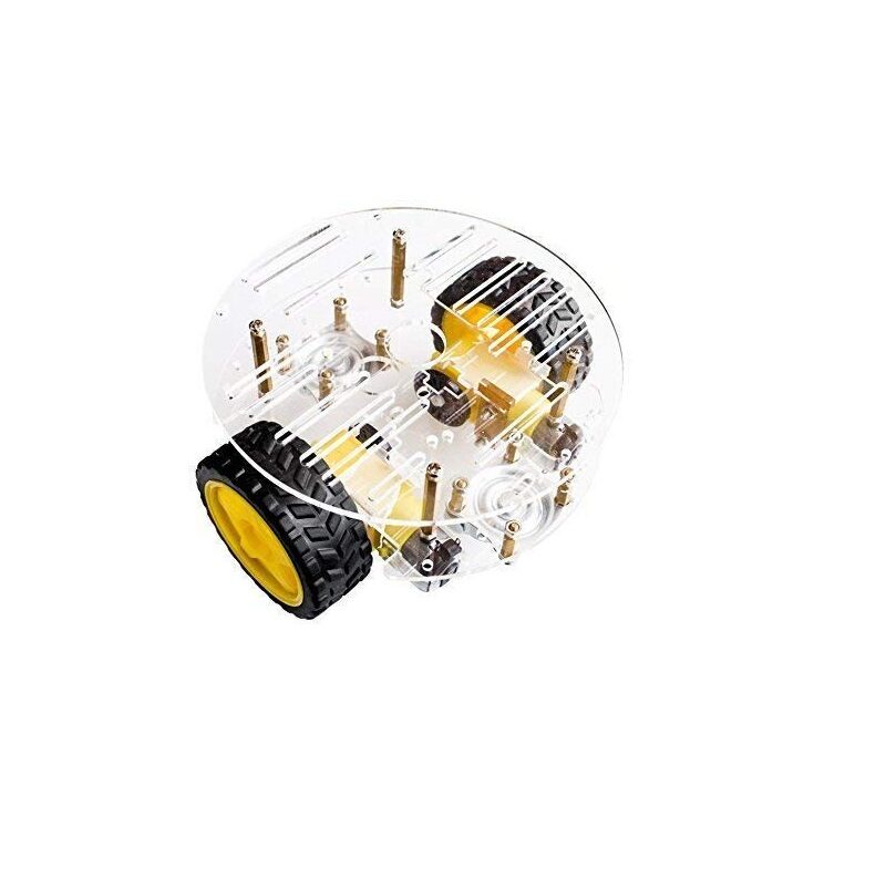
2WD Mini Round Double-Deck Smart Robot Car Chassis DIY Kit
A ready-to-assemble double-deck robot car chassis — the ideal base for your Bluetooth-controlled robot with space for Arduino, HC-05, and motor driver on separate levels.
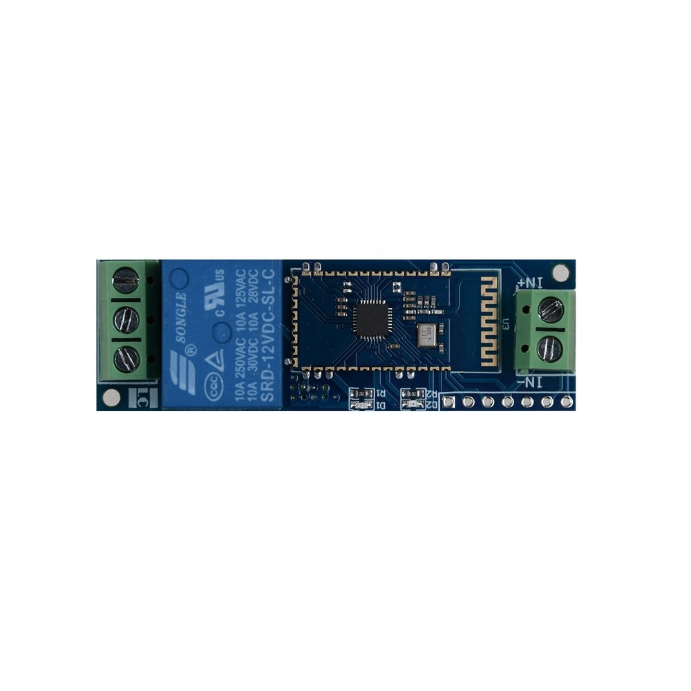
12V 1 Channel Bluetooth Relay Module
Add Bluetooth-controlled relay switching to your robot for lights, buzzers, or accessories — pairs great with the HC-05 controlled robot project.
Wiring HC-05 to Arduino
The HC-05 uses UART (serial) communication. On Arduino Uno, the hardware serial (pins 0 and 1) is shared with USB — use SoftwareSerial on pins 10 and 11 to avoid conflicts during uploading.
Connections:
- HC-05 VCC -> 5V
- HC-05 GND -> GND
- HC-05 TXD -> Arduino pin 10 (SoftwareSerial RX)
- HC-05 RXD -> Voltage divider -> Arduino pin 11 (SoftwareSerial TX)
Voltage Divider for RX pin (3.3V protection):
Arduino Pin 11 ──── 1kΩ ──┬──── HC-05 RXD
                           │
                          2kΩ
                           │
                          GND
This divides Arduino’s 5V TX down to ~3.3V for the HC-05’s RX pin. Without this, you risk damaging the module over time.
Pairing and AT Command Configuration
Before using HC-05 with your app, configure its name and PIN (optional but recommended):
- Hold the HC-05 KEY button and apply power. The LED should blink slowly (every 2 seconds) — this is AT command mode.
- Connect to Arduino and open Serial Monitor at 38400 baud, Both NL & CR selected.
- Type
AT— should respondOK. - Check current name:
AT+NAME?-> returns+NAME:HC-05 - Set a friendly name:
AT+NAME=ZboticRobot - Set PIN:
AT+PSWD=1234 - Verify baud rate:
AT+UART?-> should return+UART:9600,0,0 - Power cycle the module normally (without holding KEY). LED blinks fast (~5× per second) in pairing mode.
On your Android phone: Settings -> Bluetooth -> Scan -> Pair with ZboticRobot. Enter PIN 1234. The module LED changes to double-blink when paired.
Designing the Android App in MIT App Inventor
MIT App Inventor (appinventor.mit.edu) is a free, drag-and-drop Android app builder. No Java or Kotlin knowledge needed. Here’s how to build the control interface:
Step 1: Create a New Project
Go to appinventor.mit.edu -> Start new project -> Name it ZboticRobotControl.
Step 2: Designer — Add Components
In the Designer tab, build this layout:
- Non-visible components: BluetoothClient (from Connectivity palette)
- Screen1 layout:
- HorizontalArrangement (top): ListPicker (label: “Connect to Robot”) + Label (connection status)
- TableArrangement (3×3 grid): 5 Buttons: Forward (top centre), Left (middle left), Stop (middle centre), Right (middle right), Backward (bottom centre)
- HorizontalArrangement (bottom): Button “Horn” + Button “Lights” (optional features)
Set button sizes to 80px × 80px for comfortable thumb use on phone screens.
Step 3: Set Component Properties
- ListPicker -> Elements:
BluetoothClient.AddressesAndNames - Forward button -> Text: “▲”, BackgroundColor: Green
- Backward button -> Text: “▼”, BackgroundColor: Orange
- Left button -> Text: “◄”, Right: “►”, BackgroundColor: Blue
- Stop button -> Text: “■”, BackgroundColor: Red
App Inventor Blocks (Programming the App)
Switch to the Blocks tab. Set up the following event handlers:
Connection Logic
// ListPicker.BeforePicking:
ListPicker.Elements = BluetoothClient.AddressesAndNames

// ListPicker.AfterPicking:
IF BluetoothClient.Connect(ListPicker.Selection)
  THEN StatusLabel.Text = "Connected!"
  ELSE StatusLabel.Text = "Failed - retry"
Button Press/Release Handlers
Each button has a TouchDown event (sends command) and TouchUp event (sends Stop). This gives you hold-to-move behaviour:
// Forward.TouchDown:
BluetoothClient.SendText("F")

// Forward.TouchUp:
BluetoothClient.SendText("S")

// Left.TouchDown:
BluetoothClient.SendText("L")

// Left.TouchUp:
BluetoothClient.SendText("S")

// Right.TouchDown:
BluetoothClient.SendText("R")

// Right.TouchUp:
BluetoothClient.SendText("S")

// Backward.TouchDown:
BluetoothClient.SendText("B")

// Backward.TouchUp:
BluetoothClient.SendText("S")

// Stop.Click:
BluetoothClient.SendText("S")

// Horn.Click:
BluetoothClient.SendText("H")

// Lights.TouchDown:
BluetoothClient.SendText("O")   // lights On

// Lights.TouchUp:
BluetoothClient.SendText("X")   // lights Off
Build the APK: Build -> App (provide QR code or download APK). Install on your Android phone (allow Unknown sources in Settings -> Security).
Arduino Code: Receiving and Acting on Commands
The Arduino listens for single character commands on the SoftwareSerial port and executes motor actions accordingly:
#include <SoftwareSerial.h>

SoftwareSerial BT(10, 11);  // RX, TX (HC-05 TX -> pin 10, HC-05 RX -> pin 11)

// Motor pins
#define IN1 2
#define IN2 3
#define IN3 4
#define IN4 5
#define ENA 6
#define ENB 7
#define HORN_PIN 8
#define LED_PIN 13

void setup() {
  Serial.begin(9600);    // USB debug
  BT.begin(9600);        // Bluetooth serial
  for (int p : {IN1,IN2,IN3,IN4,ENA,ENB,HORN_PIN,LED_PIN})
    pinMode(p, OUTPUT);
  analogWrite(ENA, 200);
  analogWrite(ENB, 200);
  Serial.println("Robot ready. Waiting for Bluetooth...");
}

void stopMotors() {
  for (int p : {IN1,IN2,IN3,IN4}) digitalWrite(p, LOW);
}
void forward()    { digitalWrite(IN1,1);digitalWrite(IN2,0);digitalWrite(IN3,1);digitalWrite(IN4,0); }
void backward()   { digitalWrite(IN1,0);digitalWrite(IN2,1);digitalWrite(IN3,0);digitalWrite(IN4,1); }
void turnLeft()   { digitalWrite(IN1,0);digitalWrite(IN2,1);digitalWrite(IN3,1);digitalWrite(IN4,0); }
void turnRight()  { digitalWrite(IN1,1);digitalWrite(IN2,0);digitalWrite(IN3,0);digitalWrite(IN4,1); }

void loop() {
  if (BT.available()) {
    char cmd = BT.read();
    Serial.print("CMD: "); Serial.println(cmd);  // debug

    switch (cmd) {
      case 'F': forward();   break;
      case 'B': backward();  break;
      case 'L': turnLeft();  break;
      case 'R': turnRight(); break;
      case 'S': stopMotors();break;
      case 'H':  // Horn
        tone(HORN_PIN, 1000, 200);
        break;
      case 'O':  // Lights on
        digitalWrite(LED_PIN, HIGH);
        break;
      case 'X':  // Lights off
        digitalWrite(LED_PIN, LOW);
        break;
    }
  }
}
Upload the sketch via USB (disconnect HC-05 RX/TX during upload to avoid interference). Reconnect HC-05 after upload.
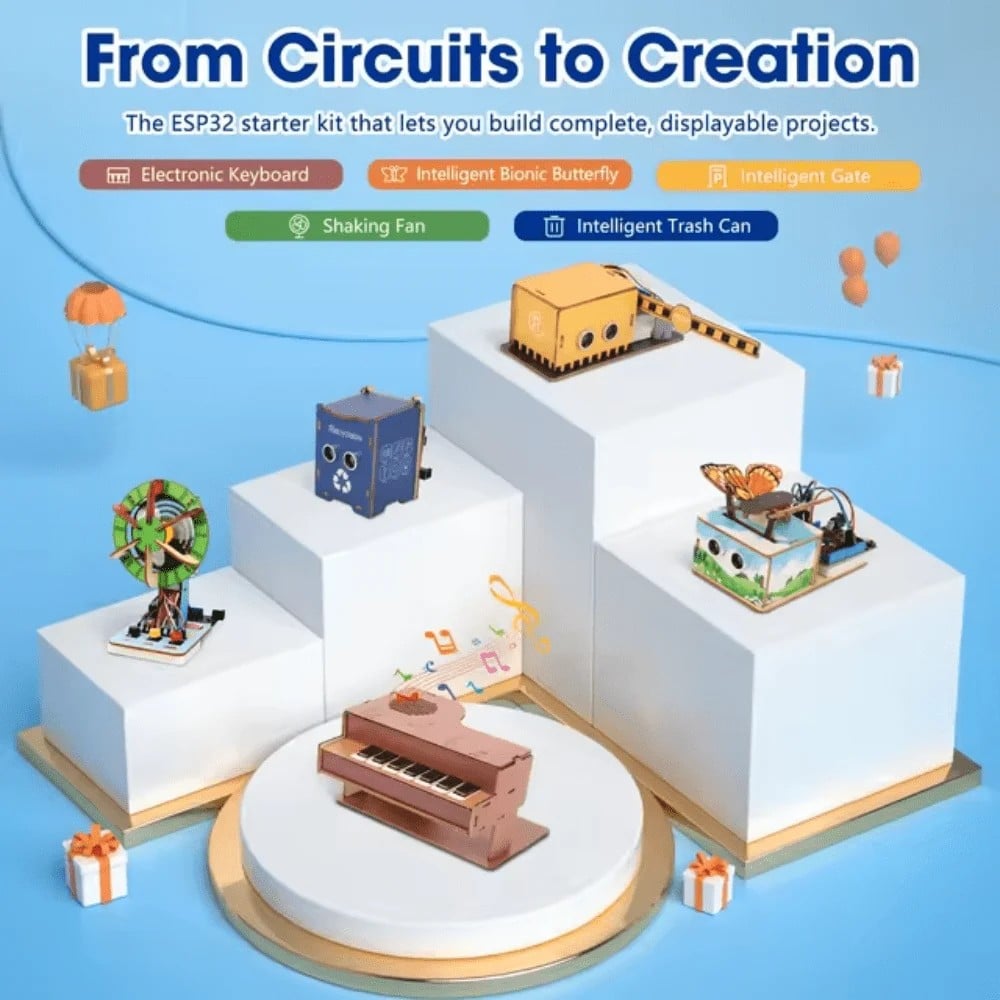
ACEBOTT ESP32 Basic Starter Kit (Project Expansion Pack) – QE201
Upgrade your Bluetooth robot project with this ESP32 kit that includes built-in WiFi and BLE — take your robot from HC-05 to native Bluetooth Low Energy control.
Testing and Debugging
Work through these debugging steps if your robot doesn’t respond as expected:
- App can’t find HC-05: Check that HC-05 is powered and LED is blinking fast. Make sure you’ve paired the device in Android Bluetooth settings first — App Inventor’s ListPicker only shows already-paired devices.
- Connected but robot doesn’t move: Check that Arduino is receiving data. Open Serial Monitor (disconnect HC-05 first) and temporarily wire buttons to hardware serial to test. Ensure SoftwareSerial uses correct pin numbers.
- Motors run but wrong direction: Swap the two wires of the affected motor at the L298N terminal. Or swap IN1/IN2 logic in code.
- Robot responds then stops responding: Bluetooth connection dropped. Add a “Reconnect” button in the app that calls
BluetoothClient.DisconnectthenBluetoothClient.Connect. - HC-05 LED never stops blinking fast (can’t pair): Phone Bluetooth is off, or HC-05 is in AT command mode (held KEY too long). Power cycle HC-05 without holding KEY button.
Project Upgrades and Feature Ideas
Once the basic robot works, here are exciting upgrades to try:
- Speed control slider: Add a Slider component in App Inventor. Send its value (0–255) as text to Arduino and use
analogWrite(ENA, value)for variable speed. - Joystick control: Use the Canvas component with a draggable circle as a virtual joystick. Calculate X/Y from touch position and send as a comma-separated string for proportional steering.
- Sensor feedback: Add HC-SR04 to the robot. Arduino sends distance readings back to the app via
BT.println(distance). App Inventor reads it withBluetoothClient.ReceiveText()and shows it on a Label. - Upgrade to ESP32: Replace Arduino + HC-05 with an ESP32. Use native BLE and build a React Native or Flutter app for more modern control. ESP32 also adds WiFi for future upgrades.
- Voice control: MIT App Inventor includes a SpeechRecognizer component. Convert “forward”, “stop”, “left”, “right” voice commands to Bluetooth signals for hands-free robot control.
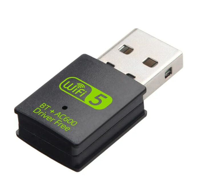
2-in-1 USB Bluetooth + WiFi Adapter (600Mbps, BT5.0)
For Raspberry Pi-based robot builds: adds Bluetooth 5.0 and 5GHz WiFi simultaneously. Great for upgrading from HC-05 to a dual-comms robot platform.
Frequently Asked Questions
- Can I use HC-06 instead of HC-05?
- Yes, HC-06 works identically for slave-mode Bluetooth serial. The difference is HC-06 can only be a slave (your phone connects to it), while HC-05 can be configured as master or slave. For this project, either works. HC-06 is slightly simpler since it has no mode button.
- Why do I need to disconnect HC-05 during Arduino upload?
- HC-05’s TX/RX pins conflict with the Arduino’s hardware serial used for uploading. If HC-05 is connected to pins 0/1, the bootloader won’t receive the upload correctly. Using SoftwareSerial on pins 10/11 avoids this, but keep the HC-05 powered off or disconnected during uploads to be safe.
- Can I control the robot with an iPhone?
- MIT App Inventor creates Android APKs only. For iOS, use Bluetooth LE (BLE) with an ESP32 replacing Arduino + HC-05, and use the nRF Toolbox or a custom Swift/React Native app. iOS does not support Bluetooth Classic SPP that HC-05 uses.
- What is the maximum reliable range of HC-05?
- In open space, 10 metres is typical. Inside buildings with walls, expect 5–7 metres reliable range. Obstacles, metal structures, and WiFi interference reduce range. For longer range, upgrade to an nRF24L01 radio (100m+) or LoRa module.
- The robot keeps stopping when I release a button. How do I make it keep moving?
- Change TouchDown/TouchUp to regular Click handlers and implement a toggle: first click sends the command, second click sends Stop. Or use a dedicated Stop button separate from directional buttons, removing the TouchUp Stop event from direction buttons.
- Can I add a camera stream to the app?
- Not easily via Bluetooth — bandwidth is too low. Add a Raspberry Pi with a camera to the robot and stream video over WiFi using MJPEG or WebRTC. Display the stream in a WebViewer component in App Inventor. Control commands still go over HC-05 to Arduino.
Build Your Bluetooth Robot Today
Get robot chassis kits, Bluetooth modules, motor drivers, and all the electronics for your weekend robotics project at Zbotic India.


Add comment