
Precise angle and position measurement is at the heart of robotics, motor control, and industrial automation. The AS5600 magnetic encoder is a contactless, high-resolution absolute position sensor that has become a favourite among hobbyists and engineers alike. Unlike optical encoders that wear out or get fouled by dust, the AS5600 uses a tiny diametrically-magnetised magnet and a Hall-effect sensor array to measure shaft angle with 12-bit (4096-step) resolution—completely without physical contact.
In this comprehensive tutorial you will learn exactly how the AS5600 works, how to wire it to an Arduino, read angle data over I2C, and build practical projects like a motor feedback loop and a rotary knob interface.
1. How the AS5600 Works
The AS5600 from ams (now ams OSRAM) is a programmable Hall-effect magnetic rotary position sensor. A diametrically-magnetised cylindrical magnet is mounted on the rotating shaft directly above the IC. The chip contains four Hall elements arranged in a circle. As the magnet rotates, each Hall element outputs a different voltage proportional to the field component it senses. The on-chip CORDIC (Coordinate Rotation Digital Computer) processor calculates the arctangent of the field components to produce a 12-bit digital angle value representing 0°–359.9°.
The key advantage over incremental encoders is that it is absolute—it always knows its exact position from the moment power is applied. There is no need for a homing sequence after power loss.
Contactless Sensing Benefits
- Zero mechanical wear — ideal for 24/7 operation
- Works through a non-ferromagnetic cover (plastic, aluminium)
- Immune to dust, oil, and moisture (the IC itself, not a sealed enclosure)
- High speed: up to 11-bit output at 1 kHz
2. Key Specifications
| Parameter | Value |
|---|---|
| Supply Voltage | 3.3 V (3.0–3.6 V) |
| Resolution | 12-bit (4096 positions/revolution) |
| Output Interface | I2C (up to 1 MHz), PWM, Analog |
| I2C Address | 0x36 (fixed) |
| Angular Accuracy | < ±0.5° after calibration |
| Max Speed | ~1000 RPM (for 12-bit output) |
| Operating Temperature | −40°C to +125°C |
| Package | 8-pin SOIC / breakout boards available |
Important: The AS5600 operates at 3.3 V. If you use a 5 V Arduino (Uno, Nano), you must use a logic-level shifter on the I2C lines, or power the sensor from the Arduino’s 3.3 V pin and add 4.7 kΩ pull-ups to 3.3 V. Many breakout boards include an onboard voltage regulator and level shifter making them 5 V-compatible.
3. Wiring to Arduino
Most AS5600 breakout boards expose: VCC, GND, SCL, SDA, DIR (direction pin), and OUT (analog/PWM output). For I2C operation:
| AS5600 Pin | Arduino Uno/Nano | Notes |
|---|---|---|
| VCC | 3.3 V | Use 3.3 V pin (if breakout has regulator, use 5 V) |
| GND | GND | Common ground |
| SCL | A5 | I2C clock |
| SDA | A4 | I2C data |
| DIR | GND or 3.3 V | GND = CW positive; 3.3 V = CCW positive |
Mount a 6 mm × 2.5 mm diametrically-magnetised disc magnet directly above the centre of the IC, with an air gap of 0.5–3 mm. The magnet must be diametrically magnetised (N–S poles on opposite flat faces of the disc diameter, not the flat surface).
4. I2C Registers You Need to Know
The AS5600 has a simple I2C register map at address 0x36:
- 0x0C–0x0D — RAW_ANGLE (12-bit, 0–4095)
- 0x0E–0x0F — ANGLE (12-bit, output after gain and hysteresis)
- 0x0B — STATUS (magnet detected, too strong, too weak flags)
- 0x1B — AGC (automatic gain control value, 0–255)
- 0x1C–0x1D — MAGNITUDE
- 0x07–0x08 — ZPOS (start position for reduced range)
- 0x09–0x0A — MPOS (stop position for reduced range)
For most projects you only need to read ANGLE (0x0E–0x0F) and STATUS (0x0B).
5. Arduino Code: Reading Angle
Below is a complete Arduino sketch to read the AS5600 angle in degrees over I2C and print it to the serial monitor:
#include <Wire.h>

#define AS5600_ADDR 0x36
#define REG_STATUS  0x0B
#define REG_ANGLE_H 0x0E
#define REG_ANGLE_L 0x0F

void setup() {
  Serial.begin(115200);
  Wire.begin();
  delay(100);
  Serial.println("AS5600 Magnetic Encoder Test");
}

uint8_t readRegister(uint8_t reg) {
  Wire.beginTransmission(AS5600_ADDR);
  Wire.write(reg);
  Wire.endTransmission(false);
  Wire.requestFrom(AS5600_ADDR, 1);
  return Wire.read();
}

uint16_t readAngleRaw() {
  uint8_t hi = readRegister(REG_ANGLE_H);
  uint8_t lo = readRegister(REG_ANGLE_L);
  return ((uint16_t)(hi & 0x0F) << 8) | lo;
}

void loop() {
  uint8_t status = readRegister(REG_STATUS);
  bool magnetDetected = (status & 0x20) != 0;
  bool tooWeak       = (status & 0x10) != 0;
  bool tooStrong     = (status & 0x08) != 0;

  if (!magnetDetected) {
    Serial.println("ERROR: No magnet detected!");
  } else if (tooWeak) {
    Serial.println("WARNING: Magnet too weak — move closer");
  } else if (tooStrong) {
    Serial.println("WARNING: Magnet too strong — move further away");
  } else {
    uint16_t raw = readAngleRaw();
    float degrees = raw * (360.0f / 4096.0f);
    Serial.print("Angle: ");
    Serial.print(degrees, 2);
    Serial.println(" deg");
  }
  delay(50);
}
Open the Serial Monitor at 115200 baud and slowly rotate your shaft. You should see smooth degree readings from 0 to 359.9 and back. The STATUS check is crucial — always verify the magnet is correctly detected before trusting angle data.
Using the AS5600 Library (Optional)
For convenience, install the AS5600 library by Rob Tillaart from the Arduino Library Manager. It wraps all register operations:
#include "AS5600.h"
AS5600 encoder;
void setup() { Wire.begin(); encoder.begin(4); } // 4 = direction pin
void loop() { Serial.println(encoder.readAngle() * AS5600_RAW_TO_DEGREES); delay(50); }
6. Magnet Placement and Calibration
The quality of your readings depends almost entirely on magnet placement. Follow these guidelines:
- Axial alignment: Centre the magnet directly over the IC. Off-centre placement causes a sinusoidal error repeating once per revolution.
- Air gap: Start at 1–1.5 mm and monitor the AGC register. AGC ~128 (midrange) indicates ideal flux density. Below 64 → too strong; above 192 → too weak.
- Magnet grade: Use N35–N52 neodymium, 6 mm diameter, 2.5 mm height. Smaller magnets need to be closer; larger magnets further away.
- ZPOS / MPOS programming: You can program start and stop positions via I2C to map a sub-range of rotation (e.g., 0°–180°) to the full 0–4095 output. This improves resolution within the operating range.
7. Real-World Project Ideas
A. BLDC Motor Closed-Loop Control
Mount the AS5600 on the motor shaft. Use the angle reading as feedback for a PID controller. At 50 Hz loop rate you get 0.09° resolution — enough for precise servo-style position control of a brushless motor with an ESC or dedicated motor driver.
B. Rotary Encoder Knob for UI
Use the AS5600 as a high-quality rotary input device. Unlike mechanical incremental encoders, it has no detents, no bounce, and reports absolute position. Scroll menus, control volume, or navigate a display with silky-smooth accuracy.
C. Robotic Joint Angle Feedback
Place an AS5600 at each robot arm joint. Read all sensors over a multiplexed I2C bus (TCA9548A multiplexer for multiple AS5600s at the same address). Feed joint angles to inverse kinematics calculations for precise end-effector positioning.
D. Gimbal Stabilisation
Combine AS5600 data with an IMU (MPU6050) for gimbal feedback. The encoder gives fast shaft position; the IMU gives absolute attitude. The combination enables extremely stable camera platforms.
E. Throttle / Steering Position Sensor
Replace potentiometers in RC vehicles or e-bikes with an AS5600. The contactless sensing eliminates the wear and noise problems that plague pots in high-vibration environments.
8. Tips and Troubleshooting
- I2C not responding: Check 3.3 V supply. Many beginners connect 5 V directly, latching the I2C lines or damaging the IC. If your breakout has a built-in regulator, 5 V is fine on VCC.
- Noisy readings: Add a 100 nF ceramic capacitor between VCC and GND as close to the IC as possible.
- Reading jumps at 0°/360° boundary: Implement software rollover handling. When reading goes from 350° to 10° the delta is −340° not +20°. Compare consecutive readings and adjust.
- Multiple AS5600s: All share I2C address 0x36. Use an I2C multiplexer (TCA9548A) to connect more than one.
- Magnetic interference: Keep motor windings, iron cores, and strong magnetic fields away from the IC. At least 20 mm clearance from motor stator.
- Speed limitation: At 12-bit resolution the maximum update rate is about 1 kHz. For higher speed, switch to 10-bit or 8-bit mode via the CONF register.
9. Sensors Available on Zbotic
While working on AS5600 projects you will likely need additional sensors for your build. Here are some quality options from Zbotic:
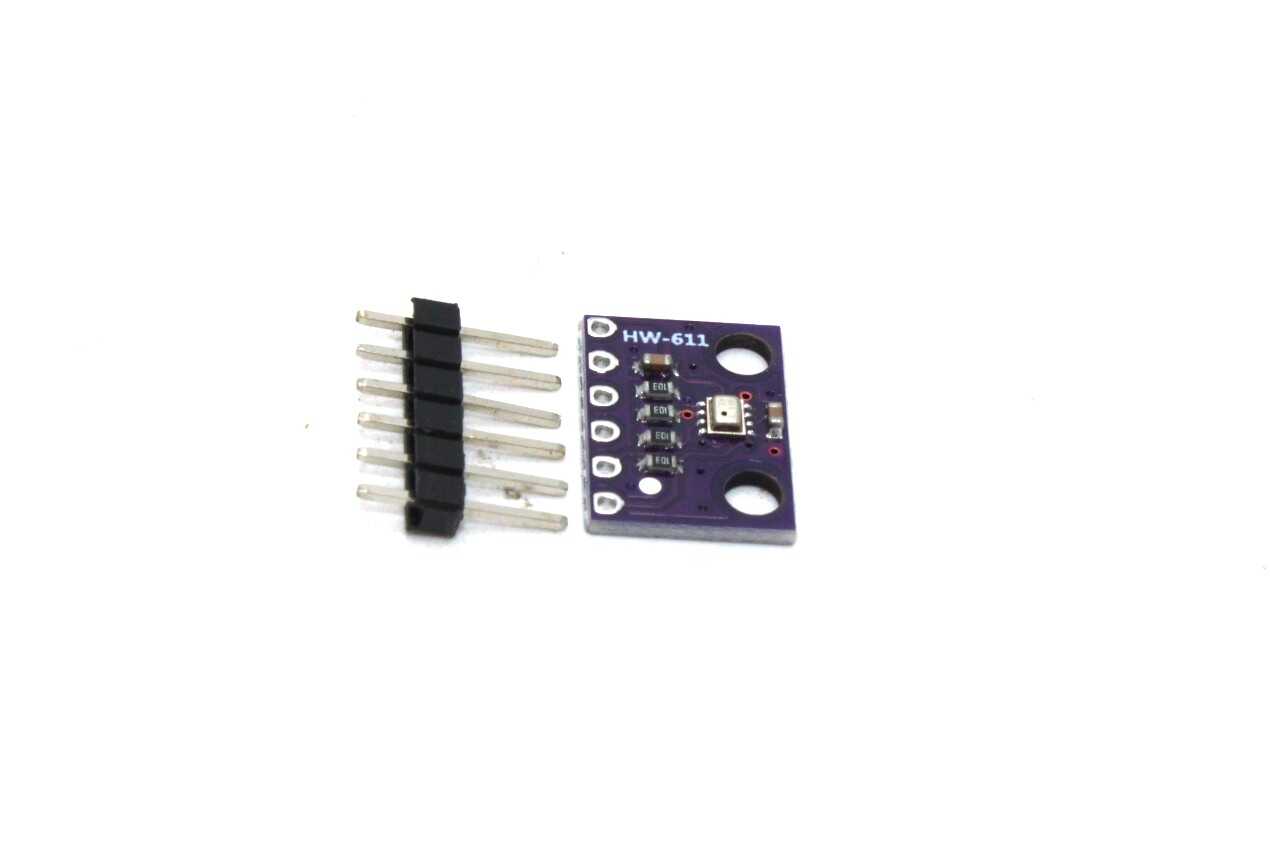
BMP280 Barometric Pressure and Altitude Sensor I2C/SPI Module
Add environmental sensing to your AS5600 projects. The BMP280 shares the I2C bus and provides pressure and altitude data — great for drone flight controllers.
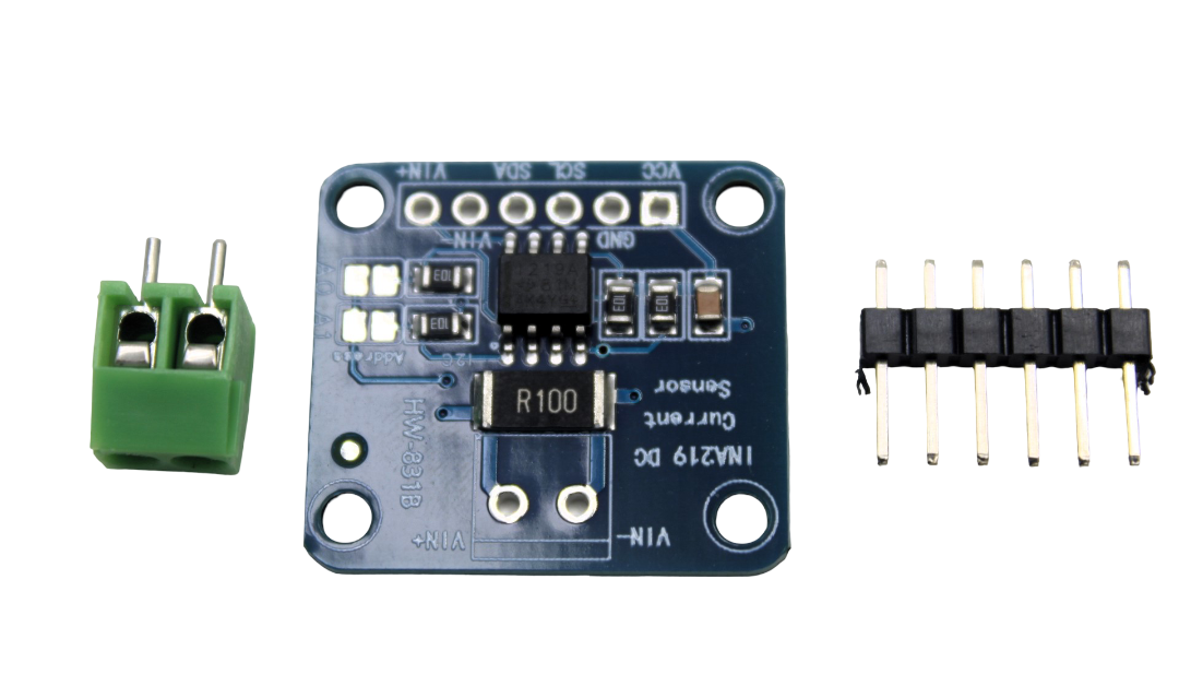
CJMCU-219 INA219 I2C Bi-directional Current/Power Monitoring Module
Monitor motor current alongside position data for complete motor feedback. I2C interface co-exists with the AS5600 on the same bus.
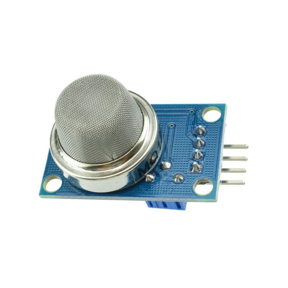
MQ-135 Air Quality / Gas Detector Sensor Module
Expand your sensor projects. The MQ-135 adds air quality measurement and pairs well with any Arduino-based sensing platform.
10. Frequently Asked Questions
Q: Can I use the AS5600 with a 5 V Arduino?
Yes, but you need to manage voltages carefully. The AS5600 IC itself runs on 3.3 V. Most breakout boards include a 3.3 V regulator and I2C level shifters, making them safe to connect directly to a 5 V Arduino. Check your specific breakout board’s datasheet before wiring.
Q: What magnet should I use with the AS5600?
Use a diametrically-magnetised neodymium disc magnet, 6 mm diameter and 2.5 mm thick (N35–N52 grade). The word “diametrically” is critical — the N and S poles must be on opposite sides of the disc diameter, not the flat faces. Standard axially-magnetised magnets will not work correctly.
Q: How accurate is the AS5600?
With optimal magnet placement, typical accuracy is ±0.5°. Electrical noise, magnet eccentricity, and nearby ferromagnetic materials can degrade this. In practice, most projects achieve ±1° or better. The 4096-step resolution gives ~0.088° theoretical resolution.
Q: Can I use multiple AS5600 sensors on one I2C bus?
The AS5600 has a fixed I2C address of 0x36 and no address-select pin. To use multiple sensors, use an I2C multiplexer such as the TCA9548A, which lets you enable each sensor on a separate channel while keeping the bus address unique.
Q: What is the difference between RAW_ANGLE and ANGLE registers?
RAW_ANGLE is the direct output of the CORDIC processor before any processing. ANGLE is the output after applying hysteresis and the programmed start/stop positions (ZPOS/MPOS). For most projects, read ANGLE for a cleaner, filtered value. RAW_ANGLE is useful for diagnostics.
Q: Can the AS5600 measure multi-turn position?
No. The AS5600 is a single-turn absolute encoder — it measures 0° to 359.9°. For multi-turn tracking you must count full revolutions in software and add them to the angle reading. The AS5048 and AS5147 are similar sensors with multi-turn support.
Ready to Build Your Position-Sensing Project?
Zbotic stocks a wide range of sensors and modules for robotics, automation, and IoT projects. Find everything you need to bring your build to life.


Add comment