
A basic on/off line follower lurches down the track, overshooting curves and oscillating wildly at speed. Implement a proper Arduino PID line follower and the same chassis becomes a smooth, fast, competition-ready robot that stays locked to the line even at maximum motor PWM. This tutorial covers everything: sensor arrays, PID theory, the complete line follower faster code implementation, and a systematic tuning procedure — so you can dial in Kp, Ki, and Kd values without guessing.
Table of Contents
- Why PID Instead of On/Off Control?
- Choosing and Wiring the Sensor Array
- Calculating Line Position from Sensors
- PID Controller Theory (Simplified)
- Complete Arduino PID Line Follower Code
- Systematic PID Tuning Procedure
- Speed Optimisation Techniques
- Advanced Techniques: Braking, Curves, and Crossings
- Frequently Asked Questions
Why PID Instead of On/Off Control?
A simple on/off (bang-bang) controller turns the robot left when it detects it is going right, and right when going left. At low speed this works acceptably. Increase motor PWM above 40% and the robot starts to oscillate — it overcorrects, crosses the line, overcorrects again, and rapidly loses tracking at curves.
A PID (Proportional-Integral-Derivative) controller calculates a continuous correction signal proportional to the magnitude of the error, its accumulated history, and its rate of change. The result is a steering correction that is large when far from the line, smoothly decreasing as the robot approaches centre — eliminating overshoot and oscillation at high speed.
In competitive robotics (e-Yantra, NIT circuit competitions, IIT techfests), PID line followers run at 60–80% motor PWM where bang-bang robots fail completely. PID is the difference between a 10-second lap and a 4-second lap on the same hardware.

2WD Mini Round Double-Deck Smart Robot Car Chassis DIY Kit
Compact 2WD chassis — the standard platform for Arduino line follower robots. Double-deck acrylic frame provides mounting space for Arduino, battery, and sensor array.
Choosing and Wiring the Sensor Array
Sensor count directly affects PID resolution. More sensors = more position granularity = better PID performance at speed:
- 3 sensors — beginner level. Only 5 distinct positions (−2, −1, 0, +1, +2). Adequate for slow speeds.
- 5 sensors — intermediate. 9 positions (−4 to +4). Good for moderate competition speed.
- 8 sensors — competition level. Smooth weighted position calculation. Best PID performance.
Mount the sensor array at the front underside of the chassis, 3–8 mm above the track surface. Lower mounting gives sharper readings but risks ground contact on uneven floors. Space sensors 10–12 mm apart for a 20–25 mm black line width.
Wire each IR sensor’s digital output to an Arduino digital pin. Use Arduino Uno pins D2–D9 for 8 sensors. Power sensors from the 5V rail and add a 100 Ω series resistor on the IR LED side to limit current.
Calculating Line Position from Sensors
The key to smooth PID is converting the binary sensor readings into a continuous position value. Use weighted average position:
// Sensor weights: leftmost = -3500, rightmost = +3500
const int weights[] = {-3500, -2500, -1500, -500, 500, 1500, 2500, 3500};

int readPosition() {
  int sum = 0, count = 0;
  for (int i = 0; i < 8; i++) {
    if (digitalRead(sensorPins[i]) == LOW) {  // LOW = on black line
      sum   += weights[i];
      count += 1;
    }
  }
  if (count == 0) return lastPosition;  // All white: keep last known position
  lastPosition = sum / count;
  return lastPosition;
}
This produces a continuous position value from −3500 (hard left) through 0 (centred) to +3500 (hard right). Feeding this as the error signal into PID gives dramatically smoother correction than a simple 3-state approach.
PID Controller Theory (Simplified)
The PID output is computed as:
output = Kp × error + Ki × integral + Kd × derivative
- P (Proportional) — steers harder when further from centre. Too high: oscillation. Too low: sluggish correction.
- I (Integral) — corrects for systematic bias (e.g., one motor slightly faster than the other). Too high: overshoot and slow drift. For line followers, Ki is often near zero.
- D (Derivative) — dampens the correction as the robot approaches centre. Prevents overshoot. The key to fast, smooth tracking.
For most Arduino line followers, Ki is set to 0 or a very small value. The real tuning is in Kp and Kd. A good starting ratio is Kd = 5 × Kp to 15 × Kp.
Complete Arduino PID Line Follower Code
// ============================================================
// Arduino PID Line Follower — Zbotic.in Tutorial
// ============================================================
#include <Arduino.h>

// Motor pins (L298N)
#define ENA 5   // PWM
#define ENB 6   // PWM
#define IN1 7
#define IN2 8
#define IN3 9
#define IN4 10

// Sensor pins (8 sensors)
const int sensorPins[] = {A0, A1, A2, A3, 2, 3, 4, 11};
const int weights[]    = {-3500,-2500,-1500,-500,500,1500,2500,3500};

// PID constants — TUNE THESE
float Kp = 0.06;
float Ki = 0.0001;
float Kd = 0.7;

int   baseSpeed   = 180;  // 0-255 PWM
int   maxSpeed    = 255;
int   lastError   = 0;
float integral    = 0;
int   lastPosition = 0;

void setMotors(int leftPWM, int rightPWM) {
  leftPWM  = constrain(leftPWM,  0, maxSpeed);
  rightPWM = constrain(rightPWM, 0, maxSpeed);
  analogWrite(ENA, leftPWM);
  analogWrite(ENB, rightPWM);
  digitalWrite(IN1, HIGH); digitalWrite(IN2, LOW);
  digitalWrite(IN3, HIGH); digitalWrite(IN4, LOW);
}

int readPosition() {
  int sum = 0, count = 0;
  for (int i = 0; i < 8; i++) {
    if (digitalRead(sensorPins[i]) == HIGH) {
      sum   += weights[i];
      count += 1;
    }
  }
  if (count == 0) return lastPosition;
  lastPosition = sum / count;
  return lastPosition;
}

void setup() {
  for (int i = 0; i < 8; i++) pinMode(sensorPins[i], INPUT);
  pinMode(ENA,HIGH); pinMode(ENB,HIGH);
  pinMode(IN1,OUTPUT); pinMode(IN2,OUTPUT);
  pinMode(IN3,OUTPUT); pinMode(IN4,OUTPUT);
}

void loop() {
  int position = readPosition();
  int error    = position;  // 0 = centre line = no error

  integral   += error;
  integral    = constrain(integral, -3000, 3000);  // Anti-windup
  int deriv   = error - lastError;

  float correction = Kp * error + Ki * integral + Kd * deriv;

  int leftSpeed  = baseSpeed + correction;
  int rightSpeed = baseSpeed - correction;

  setMotors(leftSpeed, rightSpeed);
  lastError = error;
  // No delay() — loop as fast as possible for maximum control rate
}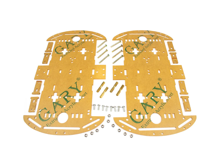
4 Wheels Car Chassis Acrylic Frame
Wide 4WD acrylic chassis with extra mounting holes — perfect for an 8-sensor array at the front and space for a LiPo battery at the rear to optimise weight distribution.
Systematic PID Tuning Procedure
Follow this procedure in order — do not skip steps:
Step 1: Set Ki = Kd = 0. Tune Kp only.
Increase Kp from 0 in small steps (0.01) until the robot follows a straight line but starts to oscillate on curves. Note this value as Kp_osc. Set Kp = 0.5 × Kp_osc as your working Kp.
Step 2: Add Kd. Tune for damping.
With Kp set, increase Kd from 0. Start at Kd = Kp × 5. The oscillation should reduce. Keep increasing Kd until oscillation disappears and the robot tracks smoothly. Watch for over-damping: the robot becomes slow to react to curves.
Step 3: Increase base speed.
Raise baseSpeed by 10–15 PWM units at a time. Each speed increase may require slight Kp and Kd re-tuning. Competition robots typically run at 200–240 PWM on the straight sections.
Step 4: Add Ki only if there is drift.
If the robot consistently runs left or right on a straight line with no control input, a small Ki value (0.0001–0.001) corrects the imbalance. Keep integral anti-windup clamping in the code to prevent integral windup on long straights.
Starting values that work on most 2WD chassis: Kp = 0.06, Ki = 0.0001, Kd = 0.7, baseSpeed = 180. These are good starting points — your chassis will need adjustment.
Speed Optimisation Techniques
Beyond PID tuning, these techniques push performance further:
- Eliminate delay() from the loop — every millisecond of delay is a meter of uncontrolled travel at speed. The main loop should run in pure polling mode.
- Direct port manipulation — replace
digitalRead()with direct port register reads. Reads all 8 sensors simultaneously in a single instruction, reducing sensor read time from ~200 μs to ~2 μs. - Variable speed on curves — detect when the position error is large (|error| > 1500) and reduce baseSpeed automatically. Accelerate back to full speed when error drops below 300.
- Low-friction wheels — wheel material affects traction at high speed. Replace stock rubber wheels with Mecanum or polyurethane-coated wheels for lower rotational inertia.
- Weight distribution — place the battery directly over the drive axle. Front-heavy robots understeer; rear-heavy robots oversteer.
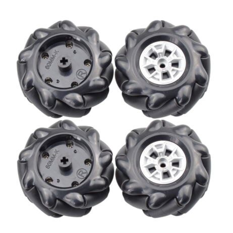
60MM-K Mecanum Wheel (Pack of 4) – Black
60mm mecanum wheels with 6.7mm hex coupling. Lower rolling resistance than rubber wheels and compatible with standard robot car motor shafts for direct upgrade.
Advanced Techniques: Braking, Curves, and Crossings
Active Braking
At high speed, coasting through corners causes the robot to overshoot. Implement active braking at curves by momentarily setting the inner motor to LOW instead of just reducing its PWM. Active braking provides 3–5× more stopping torque than PWM reduction alone.
Curve Speed Profiling
Profile the track in a calibration run at low speed. Store the error magnitude at each position along the track. In the competition run, use the stored profile to pre-emptively slow down 50 ms before a known tight curve, then accelerate back as the curve exits.
Handling Intersections and Crossings
When all sensors go dark (no black detected for > 3 ms at speed), the robot has hit a gap or crossing. Common strategies:
- Last-error extrapolation — continue turning in the direction of the last non-zero error.
- Straight-through — drive forward at reduced speed for a fixed time (e.g., 80 ms) to cross the intersection, then resume PID.
- Gap bridging — detect the direction the last sensor triggered and interpolate forward.
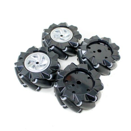
80mm-A Mecanum Wheel (Pack of 4) – Black
Larger 80mm mecanum wheels for higher top speed on line follower chassis. 6.7mm hex coupling fits most DC gear motor shafts used in robot car kits.
Frequently Asked Questions
What are good starting Kp, Ki, Kd values for a 2WD line follower?
Kp = 0.06, Ki = 0.0001, Kd = 0.7 with a base speed of 180 PWM (out of 255) is a reliable starting point for a standard 2WD chassis with 5–8 IR sensors. Always tune on your actual track — surface reflection varies significantly.
Why does my line follower oscillate even after increasing Kd?
Oscillation despite high Kd usually indicates the loop is running with a delay() that is too long. Each delay introduces dead time that makes derivative action ineffective. Remove all delays and let the loop run at full speed (typically 2,000–5,000 Hz on Arduino Uno).
How many sensors do I need for a fast competition line follower?
Eight sensors are the sweet spot for competition. Five sensors work well at moderate speed. Three sensors are adequate only for beginner demonstrations — they lack the resolution for smooth PID at high speed.
Can I use analog sensors instead of digital for better PID?
Yes — analog IR sensors (TCRT5000 read via analogRead) give a continuous value per sensor rather than binary. This gives the weighted average calculation higher resolution. The trade-off is slower reading time (~100 μs per analog read vs ~2 μs for digital).
What is integral windup and how do I prevent it?
Integral windup occurs when the integral term accumulates to a very large value during a period when the robot is off the track or stuck. When it returns to the line, the accumulated integral causes a large overcorrection. Prevent it with clamping: integral = constrain(integral, -3000, 3000).
Build a competition-winning line follower! Get your chassis, wheels, and sensor components from Zbotic’s robotics category — fast shipping across India, quality components at maker-friendly prices. Your PID robot is waiting!


Add comment