
Table of Contents
- Why Sensor Output Type Matters
- Analog Sensor Output Fundamentals
- Digital Sensor Output Fundamentals
- ADC Resolution: Bits, Steps, and Voltage
- ADC on Arduino: 10-bit and 12-bit Compared
- PWM, I2C, SPI, UART — Digital Protocol Overview
- Noise, SNR, and Effective Number of Bits (ENOB)
- How to Choose: Analog vs Digital for Your Project
- Code Examples for Both Output Types
- Advanced Topics: Oversampling, Averaging, and Filtering
- Frequently Asked Questions
Why Sensor Output Type Matters
Every sensor you connect to an Arduino or microcontroller produces an output signal. That signal is either analog — a continuously variable voltage — or digital — a discrete representation using defined voltage levels or serial protocols. Choosing the right sensor output type for your application affects measurement accuracy, noise immunity, wiring complexity, processor load, and ultimately the reliability of your project.
Beginners often grab whatever sensor is cheapest without considering output type, only to discover that their temperature reading fluctuates wildly (analog noise), their digital sensor requires a library that does not fit in flash memory, or their ADC resolution is too coarse to detect the small changes they care about.
This guide breaks down the fundamentals clearly, with concrete numbers and Arduino code examples, so you can make the right choice every time.
Analog Sensor Output Fundamentals
An analog sensor produces a voltage (or occasionally a current) that varies continuously and proportionally with the measured physical quantity. The LM35 temperature sensor produces 10mV per degree Celsius. A photodiode current amplifier produces a current proportional to light intensity. A strain gauge Wheatstone bridge produces a millivolt differential proportional to applied force.
Advantages of Analog Output
- Simplicity: Wire the output to an ADC pin and you are done. No protocol, no library, no timing requirements.
- Bandwidth: Analog signals can change at any rate — limited only by the sensor’s physical response time, not a communication protocol’s data rate.
- Legacy compatibility: Legacy industrial systems (4–20mA loops, 0–5V process signals) use analog as the universal standard.
- Continuous representation: No quantisation in the sensor itself — all quantisation happens in your ADC, and you can upgrade the ADC independently.
Disadvantages of Analog Output
- Noise susceptibility: Any electromagnetic interference in the cable or circuit couples directly into the signal. Longer cables mean more noise.
- Ground reference dependency: Measurement accuracy depends on the sensor and ADC sharing a perfectly stable, identical ground reference. Any ground noise adds directly to measurement error.
- Requires ADC: Your microcontroller needs an ADC input channel for each analog sensor — a resource that is often limited.
- Calibration drift: Component aging and temperature cause the analog signal chain to drift over time.
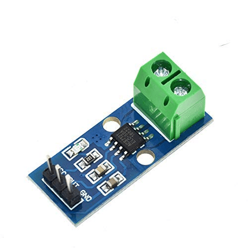
30A Range Current Sensor Module ACS712
A classic analog output current sensor — its 0–5V output maps directly to the full ADC range, making it a great example of why ADC resolution directly determines measurement precision.
Digital Sensor Output Fundamentals
A digital sensor converts the physical measurement internally and communicates the result as binary data. The sensor contains its own ADC, reference, and often a signal processor. The output arrives as a sequence of logic-level bits using a protocol like I²C, SPI, UART, or 1-Wire.
Advantages of Digital Output
- Noise immunity: Binary HIGH/LOW signals are far more immune to noise than precise analog levels. A signal that is supposed to be 3.3V but arrives at 3.1V due to noise still reads as a valid HIGH.
- Long-distance communication: Serial protocols like RS-485 can transmit digital sensor data over hundreds of metres with no noise degradation.
- Multiple sensors, one bus: I²C and 1-Wire allow many sensors to share a single pair of wires.
- Self-calibrating: Digital sensors integrate the ADC and reference; no external calibration chain to worry about.
Disadvantages of Digital Output
- Protocol overhead: Requires library code, timing-sensitive communication, and debugging tools.
- Latency: A single I²C transaction may take hundreds of microseconds — problematic for fast-changing signals.
- Fixed resolution: You cannot upgrade the sensor’s internal ADC. What the datasheet says is what you get.
ADC Resolution: Bits, Steps, and Voltage
An Analog-to-Digital Converter (ADC) maps a continuous voltage range onto a discrete integer. The resolution — measured in bits — determines how many discrete steps are available:
- 8-bit ADC → 2⁸ = 256 steps
- 10-bit ADC → 2¹⁰ = 1,024 steps
- 12-bit ADC → 2¹² = 4,096 steps
- 16-bit ADC → 2¹⁶ = 65,536 steps
- 24-bit ADC → 2²⁴ = 16,777,216 steps
LSB Voltage: The Key Calculation
The Least Significant Bit (LSB) voltage is the smallest voltage change the ADC can distinguish:
LSB voltage = Reference Voltage ÷ 2^(number of bits)
For Arduino Uno (10-bit, 5V reference):
LSB = 5V ÷ 1024 = 4.88 mV per step
For a 12-bit ADC with 3.3V reference:
LSB = 3.3V ÷ 4096 = 0.806 mV per step
For a 24-bit ADC (like the HX711 load cell amplifier) with 5V reference:
LSB = 5V ÷ 16,777,216 = 0.298 µV per step
Converting ADC Reading to Physical Units
For the LM35 temperature sensor (10mV/°C) read by Arduino’s 10-bit ADC at 5V reference:
int rawADC = analogRead(A0);           // 0 to 1023
float voltage_mV = (rawADC / 1023.0) * 5000.0;  // mV
float temperature_C = voltage_mV / 10.0;         // 10mV per °C
// Resolution: 4.88mV ÷ 10mV/°C = 0.488°C per step
The Arduino’s 10-bit ADC can only resolve temperature changes of about 0.49°C when reading the LM35 at 5V reference. To do better, use the internal 1.1V reference (reducing LSB to 1.07mV = ~0.11°C per step) or switch to a digital sensor with a higher-resolution internal ADC.
| ADC Bits | Steps | LSB (5V ref) | LM35 Temp Resolution |
|---|---|---|---|
| 8-bit | 256 | 19.5 mV | 1.95°C |
| 10-bit | 1,024 | 4.88 mV | 0.49°C |
| 12-bit | 4,096 | 1.22 mV | 0.12°C |
| 16-bit | 65,536 | 76.3 µV | 0.0076°C |
ADC on Arduino: 10-bit and 12-bit Compared
The Arduino Uno uses the ATmega328P, which has a 10-bit SAR ADC. The Arduino Due, Arduino Zero, and many ESP32 boards offer 12-bit ADCs.
Using the Internal 1.1V Reference for Better Resolution
When your sensor’s output range is small, switching to the internal 1.1V reference gives you finer resolution at the cost of a narrowed measurement window:
void setup() {
  analogReference(INTERNAL); // 1.1V reference on Uno
  // Now LSB = 1.1V / 1024 = 1.07 mV
  // LM35 resolution improves to 1.07mV / 10mV/°C = 0.107°C
}

void loop() {
  int raw = analogRead(A0);
  float temp = (raw * 1.1 / 1023.0) * 100.0; // LM35: 10mV/°C = 0.01V/°C
  // Or: temp = (raw * 0.1075); // Simplified
  Serial.println(temp);
  delay(500);
}
Warning: Never apply more than 1.1V to an analog pin when using INTERNAL reference — it will give incorrect readings (clamped to maximum). Measure your sensor’s output range first.

20A Range Current Sensor Module ACS712
Analog output current sensor for mains appliance monitoring. With a 12-bit ADC, this sensor’s 100mV/A sensitivity resolves current to better than 50mA per step.
PWM, I2C, SPI, UART — Digital Protocol Overview
Digital sensors use a variety of serial protocols. Understanding which your sensor uses determines your wiring and code approach:
I²C (Inter-Integrated Circuit)
A two-wire protocol (SDA + SCL) that supports multiple devices on the same bus. Each device has a unique 7-bit address. Data rates are typically 100 kHz (standard), 400 kHz (fast), or 1 MHz (fast-plus). Perfect for sensors where you do not need very fast sampling. Examples: BME280, TMP117, MPU6050, BH1750.
SPI (Serial Peripheral Interface)
A four-wire protocol (MOSI, MISO, SCLK, CS) that is faster than I²C but requires one CS (chip select) pin per device. Data rates reach 10+ MHz. Used for high-speed ADCs, display drivers, and SD cards. Examples: MAX31865 RTD amplifier, MCP3208 external 12-bit ADC.
1-Wire (Dallas)
A single-wire protocol that carries both power and data. Multiple devices share one wire using unique 64-bit addresses. Slow but incredibly wiring-efficient. Used almost exclusively for the DS18B20 temperature sensor family.
UART (Serial)
Asynchronous serial using TX and RX pins. Often used for sensors that output NMEA strings (GPS modules), PM2.5 dust sensors, and CO2 sensors. Requires matching baud rates between sender and receiver.
PWM (Pulse Width Modulation)
Some sensors encode their output as a PWM duty cycle. A humidity sensor might output 10% duty cycle for 10% RH and 90% for 90% RH. Measure the duty cycle using pulseIn() or hardware capture. Simple but limited in resolution (typically 8-bit equivalent).
Noise, SNR, and Effective Number of Bits (ENOB)
A 12-bit ADC does not necessarily give you 12 bits of useful information. Electronic noise in the signal chain consumes some of those bits. The Effective Number of Bits (ENOB) describes how many bits are actually noise-free:
ENOB = (SINAD - 1.76) / 6.02
Where SINAD is the Signal-to-Noise-And-Distortion ratio in dB (found in the ADC’s datasheet). A well-designed 12-bit ADC might achieve 10.5 ENOB — meaning about 1.5 bits are consumed by noise.
Practical Noise Reduction Techniques
- Add a 100nF decoupling capacitor between the sensor’s VCC and GND, placed as close to the sensor as possible. This filters high-frequency power supply noise.
- Use a separate, clean voltage reference for your ADC instead of the microcontroller’s internal reference, which is noisier.
- Twist signal and ground wires together when running longer cables. This converts common-mode interference to differential, which cancels out.
- Average multiple readings in software to reduce random noise (see the Advanced Topics section).
- Route analog signals away from digital lines on your PCB. Clocks and data lines radiate EMI that couples into analog traces.
How to Choose: Analog vs Digital for Your Project
| Requirement | Choose Analog | Choose Digital |
|---|---|---|
| Cable length > 1m | ✓ (RS-485 or 1-Wire) | |
| Many sensors, few pins | ✓ (I²C / 1-Wire) | |
| High sample rate (>1kHz) | ✓ | |
| Simple, no libraries | ✓ | |
| Low noise environment | ✓ | |
| Noisy industrial setting | ✓ | |
| High precision (<0.1°C) | ✓ (TMP117) | |
| Battery-powered remote unit | ✓ (ultra-low sleep current) |
Code Examples for Both Output Types
Reading Analog Sensor (LM35 on Arduino)
const int LM35_PIN = A0;
const float VREF = 5.0;       // Reference voltage
const int ADC_BITS = 10;      // Arduino Uno
const float LSB = VREF / (pow(2, ADC_BITS) - 1); // 4.887 mV

void setup() { Serial.begin(115200); }

void loop() {
  int raw = analogRead(LM35_PIN);
  float voltage_mV = raw * LSB * 1000.0; // In millivolts
  float temp_C = voltage_mV / 10.0;      // LM35: 10mV/°C

  Serial.print("Raw ADC: "); Serial.print(raw);
  Serial.print(" | Voltage: "); Serial.print(voltage_mV, 1); Serial.print(" mV");
  Serial.print(" | Temperature: "); Serial.print(temp_C, 1); Serial.println(" °C");

  delay(1000);
}
Reading Digital Sensor (DS18B20 via 1-Wire)
#include <OneWire.h>
#include <DallasTemperature.h>

const int ONE_WIRE_BUS = 4;
OneWire oneWire(ONE_WIRE_BUS);
DallasTemperature sensors(&oneWire);

void setup() {
  Serial.begin(115200);
  sensors.begin();
  sensors.setResolution(12); // 12-bit: 0.0625°C resolution
}

void loop() {
  sensors.requestTemperatures();
  float temp = sensors.getTempCByIndex(0);
  Serial.print("DS18B20: "); Serial.print(temp, 4); Serial.println(" °C");
  delay(1000);
}
Advanced Topics: Oversampling, Averaging, and Filtering
Oversampling: Getting More Bits from a Low-Resolution ADC
A mathematical trick: if you add N random-noise-affected samples together, you gain 0.5 bits of resolution for every 4× increase in sample count. To gain 2 extra bits (going from 10-bit to 12-bit), take 4^2 = 16 samples and sum them:
// Oversample 10-bit ADC to get 12-bit resolution
long oversampledRead(int pin, int extraBits) {
  int n = 1 << (extraBits * 2); // 4^extraBits samples
  long sum = 0;
  for (int i = 0; i < n; i++) {
    sum += analogRead(pin);
    delayMicroseconds(100); // Allow capacitor to settle
  }
  return sum >> extraBits; // Decimation shift
}

void loop() {
  long val12bit = oversampledRead(A0, 2); // 12-bit equivalent
  float voltage = (val12bit / 4095.0) * 5.0;
  Serial.println(voltage, 4);
}
This works because real noise provides the dithering needed for oversampling to succeed. In a completely noise-free system, oversampling provides no benefit. The tiny amount of ADC noise in any real circuit is actually your friend here.
Exponential Moving Average (EMA) for Smooth Readings
float emaValue = 0.0;
const float ALPHA = 0.1; // Smoothing factor: 0.0 (max smooth) to 1.0 (no smooth)

void loop() {
  float newReading = analogRead(A0) * (5.0 / 1023.0);
  emaValue = ALPHA * newReading + (1.0 - ALPHA) * emaValue;
  Serial.println(emaValue, 3);
  delay(10);
}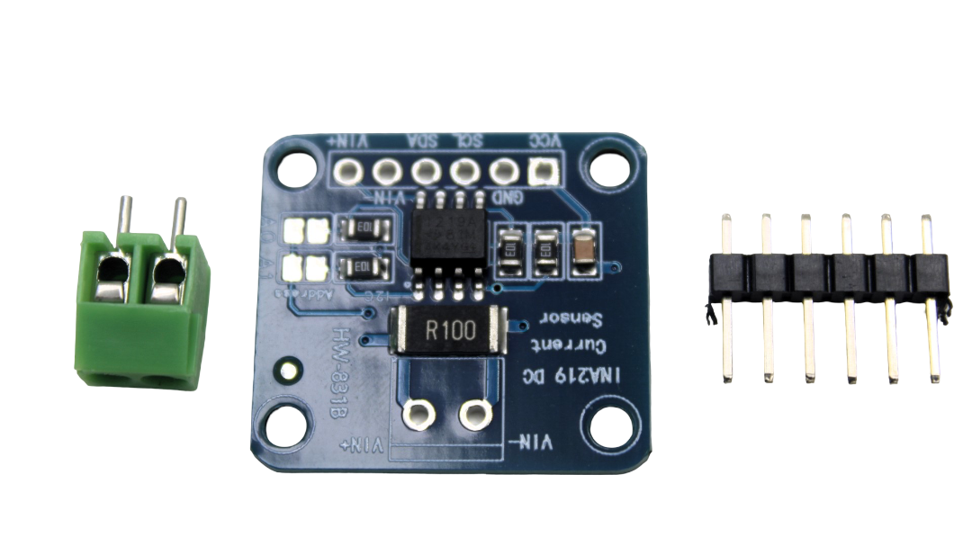
CJMCU-219 INA219 I2C Interface Bi-directional Current / Power Supply Monitoring Module
A 12-bit digital power monitor that measures voltage and current simultaneously via I2C — no external ADC needed, no noise issues, and 1% accuracy out of the box.
Frequently Asked Questions
What is the ADC resolution of Arduino Uno?
The Arduino Uno’s ATmega328P has a 10-bit ADC, giving 1,024 discrete steps. With the default 5V reference, each step represents 4.88 mV. The Arduino Due and Arduino MKR boards have 12-bit ADCs (4,096 steps), and some ESP32 configurations offer 12-bit resolution as well, though ESP32’s ADC linearity is poor in practice at the upper voltage range.
Can I use multiple analog sensors on one Arduino?
Yes. The Arduino Uno has six analog input pins (A0–A5), all multiplexed to the single internal ADC. Readings are taken sequentially. There is a small settling time needed between reading different sensors, especially if they have very different source impedances. For simultaneous sampling, use an external multi-channel ADC like the MCP3208 (8-channel, 12-bit SPI).
What causes ADC readings to fluctuate even when the sensor is not changing?
Quantisation noise (the unavoidable rounding to the nearest step), power supply noise coupling into the ADC reference, electromagnetic interference from nearby digital circuitry, and ground loops all contribute. Averaging multiple readings, adding decoupling capacitors, using a separate voltage reference, and physically separating analog and digital ground planes on a PCB all help.
Is a 12-bit ADC always better than a 10-bit ADC?
More bits give finer resolution, but only if your signal chain noise is below the LSB voltage of the higher-resolution ADC. If your analog signal has 10mV of noise and you use a 12-bit ADC with 1.22mV LSB (at 5V reference), those bottom 3 bits are just noise. In that case, the extra resolution provides no useful information. Always match ADC resolution to the signal quality you can actually achieve.
What does the I2C clock speed affect in a digital sensor?
I²C clock speed determines how fast data transfers between sensor and microcontroller. At 100 kHz (standard mode), a typical 2-byte temperature register read takes about 200 µs. At 400 kHz (fast mode), the same transfer takes ~50 µs. For most sensor applications this difference is irrelevant, since the sensor’s measurement conversion time is far longer than the communication overhead.
How do I improve Arduino ADC accuracy?
Use the Arduino’s INTERNAL 1.1V reference for small-signal sensors to get better effective resolution. Add a 100nF ceramic capacitor on the AREF pin to stabilise the reference. Average 16 or more readings using oversampling for 1–2 extra bits of effective resolution. Ensure your sensor has a low output impedance (below 10 kΩ ideally) to allow the ADC’s sample-and-hold capacitor to charge fully between readings.
Building a sensor project? Zbotic stocks analog and digital sensors, current monitors, ADC breakout boards, and all the passive components you need to build accurate measurement systems. Delivered across India. Shop Sensors & Modules at Zbotic →


Add comment