
AM Radio Receiver Circuit: Coil, Capacitor and Diode Design Explained
The AM radio receiver circuit is arguably the most fundamental RF project in electronics education, and for good reason — it demonstrates resonance, demodulation, and signal extraction with just three or four passive components. From the classic crystal set that requires no battery whatsoever, to the multi-stage transistor superheterodyne that pulls in distant stations clearly, AM radio receivers offer a fascinating study of analogue electronics. This guide explores the working principle, circuit designs, and practical construction tips for Indian electronics students and hobbyists who want to understand radio from first principles.
AM Broadcasting Basics in India
AM (Amplitude Modulation) radio broadcasting in India operates on the Medium Wave (MW) band from approximately 530 kHz to 1710 kHz, and on the Short Wave (SW) band from approximately 3 MHz to 30 MHz. All India Radio (AIR), the national public broadcaster, operates an extensive MW and SW network covering the entire subcontinent. Major cities have strong local MW transmitters — for example, AIR Delhi broadcasts on 612 kHz, AIR Mumbai on 1188 kHz, and AIR Bangalore on 720 kHz.
For a homebrew receiver, the Medium Wave band is the most practical target. Strong local transmitters with powers of 100kW to 400kW mean that even a simple crystal set can receive AIR’s MW stations clearly if you’re within 30–50 km of a transmitter. In smaller towns, you may need an amplified design. The SW band is more challenging to receive due to varying propagation conditions, but it offers the fascinating possibility of hearing international broadcasts from thousands of kilometres away.
The Crystal Set: Simplest AM Receiver
The crystal set is the purest form of AM receiver — it requires no battery, no active components, and receives power entirely from the incoming radio waves. A long wire antenna picks up RF energy; the LC tank circuit filters out a single station’s frequency; the diode detector extracts the audio information; and high-impedance headphones convert the tiny electrical signal to sound.
The name “crystal set” comes from the original galena (lead sulfide) crystal used as the detector — a primitive point-contact diode. Today we use a 1N34A germanium diode, or a 1N4148 silicon diode (though germanium is preferred for its lower forward voltage drop of ~0.3V vs ~0.7V for silicon, giving better sensitivity on weak signals).
The crystal set has two major limitations: (1) it can only receive very strong local stations because it has no amplification, and (2) it requires high-impedance crystal earphones (2000 ohm+) or a 1:100 audio transformer to drive regular 32-ohm headphones. But as a learning tool and starting point, it’s unmatched.
Core Components: Coil, Capacitor, Diode
Understanding what each component does is essential before building:
The Coil (L) — Ferrite Rod Antenna:
The antenna coil serves two purposes: it acts as a receiving antenna (the ferrite rod concentrates the magnetic component of the radio waves), and it forms one half of the LC resonant circuit. For MW reception (530–1710 kHz), a coil of approximately 55–70 turns of 26 AWG enamelled copper wire on a 10cm × 10mm ferrite rod is typical. The ferrite material increases the effective inductance (typically 220–560 µH for a complete MW coil).
The Tuning Capacitor (C) — Variable Capacitor:
A ganged variable capacitor (typically 10–365 pF range) tunes the LC circuit across the MW band. As you rotate the tuning dial, the capacitance changes, shifting the resonant frequency of the LC tank. At resonance (f = 1 / (2π√LC)), the tank circuit presents maximum impedance — effectively selecting that frequency and rejecting all others. For the full MW band of 530–1710 kHz, you need an inductance of approximately 250 µH and a capacitor that varies from about 27pF to 270pF.
The Detector Diode:
AM modulation works by varying the amplitude (envelope) of a high-frequency carrier signal. The diode rectifies the RF signal — it passes only the positive half-cycles. A filter capacitor (usually 100pF to 1nF) then smooths out the RF carrier ripple, leaving only the audio-frequency envelope. This process is called envelope detection or AM demodulation. The 1N34A germanium diode is traditional, but OA90, OA79, or even a Schottky diode (like the BAT43) can work.

0.1µF Ceramic Capacitor (Pack of 50)
Ceramic capacitors are used for audio bypass and decoupling in the transistor-amplified AM receiver. Pack of 50 for your component stock.
Circuit Diagram and Connections
Basic Crystal Set (No Battery Required):
- Antenna: 5–10 metre long wire strung outdoors or near a window. One end connects to the top of the tuning coil L1.
- Earth/Ground: A ground connection (water pipe, earth rod) connects to the circuit ground. A good earth dramatically improves sensitivity.
- Tank circuit: Tuning coil L1 and variable capacitor C1 in parallel, connected between antenna and ground.
- Diode D1: Connected from the hot end of the tank circuit (antenna side) to the audio output point.
- Filter cap C2: 220pF ceramic, from the diode anode to ground. This bypasses the RF while passing audio.
- Load resistance R1: 100kΩ from audio output to ground (sets impedance for high-Z earphones).
- Earphones: High-impedance crystal earphones connected across R1.
Amplified Crystal Set (with 1.5V Battery):
For better sensitivity with regular 32-ohm earphones or a small speaker, add a single-transistor audio amplifier after the diode detector. The detector output feeds through a 100nF coupling capacitor to the base of a BC547 transistor configured as a common-emitter amplifier with a gain of approximately 50. The collector load resistor (10kΩ) feeds the collector voltage, and the audio output is taken from the collector through another 100nF capacitor to a high-impedance headphone or a mini speaker through a small audio transformer.
Three-Transistor Amplified Receiver:
For reliable performance throughout India, a three-transistor design provides enough gain to drive a small 8-ohm speaker audibly on most AIR MW stations. The first transistor is an RF amplifier (common base configuration for low input impedance matching to the antenna), the second is the detector-amplifier stage, and the third is an audio power amplifier. This design can receive stations from 200–500 km on Medium Wave at night due to ionospheric propagation.
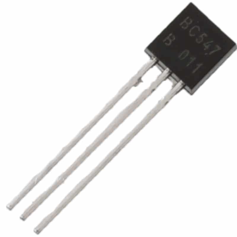
BC547 NPN 100mA Transistor TO-92 (Pack of 10)
Used as the audio amplifier stage in the amplified AM radio receiver. The BC547’s low noise makes it ideal for small-signal audio amplification after the detector.
Adding a Transistor Amplifier Stage
The basic crystal set has no amplification — it can only drive very high impedance earphones from strong local signals. Adding even one transistor stage transforms the receiver’s capability dramatically.
Single BC547 Audio Amplifier (Common Emitter):
- Supply: 1.5V (AA battery) to 9V
- Collector resistor (RC): 10kΩ
- Emitter resistor (RE): 1kΩ (unbypassed for stability)
- Base bias: R1 = 470kΩ, R2 = 47kΩ voltage divider
- Input coupling cap: 100nF from detector output to base
- Output coupling cap: 10µF to headphone or transformer
- Expected voltage gain: ~30 (30dB)
With a 9V supply and this amplifier, you can drive a 2000-ohm miniature earphone to comfortable listening volumes from any AIR MW station within 50km of its transmitter. For a small 8-ohm speaker, add an LM386 audio IC (or a second BC547 in emitter-follower configuration) as the final audio power stage — this can deliver 100–250mW to an 8-ohm speaker, which is enough for room-level listening in a quiet environment.
Automatic Gain Control (AGC) — Advanced:
In a multi-stage amplified receiver, the audio volume can vary wildly between strong local stations and weak distant ones. AGC solves this by feeding a portion of the detected audio signal back to reduce the gain of the RF stage when a strong signal is received. In simple designs, the AGC voltage is derived from the diode detector output (DC component) and fed back to the RF transistor’s base through a 100kΩ resistor, reducing its bias (and therefore gain) on strong signals.
Winding the AM Ferrite Antenna Coil
A properly wound ferrite antenna coil is the most critical component in an AM receiver. Here’s how to wind one for the MW band:
Materials needed:
- Ferrite rod: 10cm long, 10mm diameter (MW type, permeability ~200)
- 26 AWG enamelled copper wire (magnet wire)
- Paper or cardboard former (tube that fits snugly over the ferrite rod)
- Tape to secure the winding
Winding procedure:
- Make a cardboard former 2cm wide that slides smoothly on the ferrite rod. This allows you to slide the coil along the rod to fine-tune inductance.
- Wind 60 turns of 26 AWG enamelled wire in a single layer, closely wound. Tape the start and end leads.
- For a tapped coil (useful for antenna coupling and impedance matching), bring out a tap at 10 turns from the grounded end.
- After winding, scrape the enamel insulation from the last 2cm of each lead to expose bare copper. Tin with solder.
- The inductance should measure approximately 230–350 µH depending on core permeability — measure with an LCR meter if available.
To tune the full MW band, pair this coil with a 10–365 pF variable capacitor. At maximum capacitance (365pF) with a 280µH coil, the circuit resonates at about 530 kHz (bottom of MW band). At minimum capacitance (10pF), it resonates at about 3.2 MHz — this covers both MW and a portion of SW.

9V Battery Operated LCR-T4 12864 LCD Graphical Transistor Tester
Measure your hand-wound coil inductance and verify capacitor values before assembly. The LCR-T4 measures L, C, R, and tests transistors — essential for any RF project.
Troubleshooting Your AM Receiver
Here are the most common problems and solutions when building an AM crystal radio or amplified receiver:
Problem: No sound at all
Check: Is the diode installed in the correct polarity? Is your earth/ground connection solid? Try moving closer to a known AM transmitter. Test the diode with a multimeter in diode-check mode — it should show ~0.3V forward drop (germanium) or ~0.6V (silicon). Check that the variable capacitor’s moving plates don’t make electrical contact with the frame (which would short the tank circuit).
Problem: Can hear stations but they bleed into each other
This is a selectivity problem. The Q (quality factor) of your LC tank is too low. Solutions: use higher-inductance ferrite core, ensure the variable capacitor is fully functional (no leakage), and reduce antenna coupling to prevent the antenna impedance from loading the tank. Use the tapped coil approach — connect the antenna to the 10-turn tap rather than the full coil to reduce loading.
Problem: Loud hum in amplified receiver
AC hum at 50 Hz indicates a poor power supply. Replace with a fresh battery or add heavy filtering (1000µF cap across supply). Also check that the audio wiring is not running parallel to any AC mains cables.
Problem: Station volume drops when touching the coil/capacitor
Your body is being added in parallel with the tank circuit, detuning it. This suggests the coil former is slightly conductive or there are stray connections. Ensure all connections are clean solder joints with no stray copper touching adjacent tracks on the PCB.
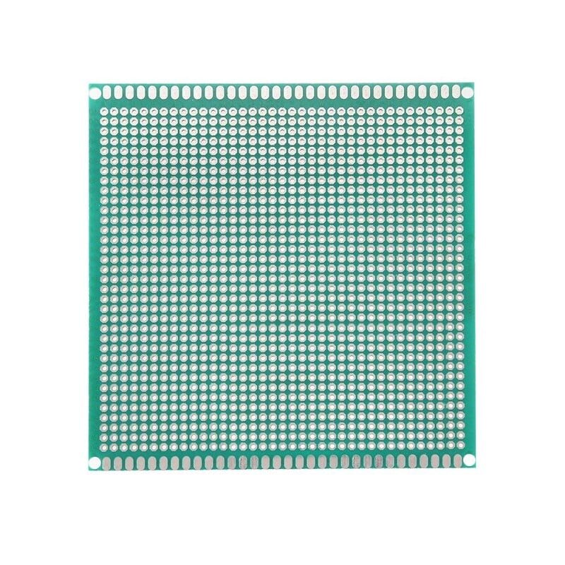
10 x 10 cm Universal PCB Prototype Board Single-Sided 2.54mm Hole Pitch
Solder your AM radio receiver permanently on this universal PCB for a stable, durable build that avoids the loose connection problems common in breadboard RF circuits.
Frequently Asked Questions
Q1: Do I need an earth ground connection for the crystal set?
A proper earth ground dramatically improves sensitivity and selectivity of a crystal set. Without it, the antenna-to-ground voltage difference is smaller, giving less signal to the detector. A long wire antenna with a good earth can make the difference between hearing a faint whisper and clear audio. Use a cold water pipe (metal, not plastic), a proper earth rod, or even several metres of wire buried 30cm underground as your earth connection.
Q2: Why use germanium diodes instead of silicon 1N4148?
Germanium diodes (1N34A, OA90) have a forward voltage drop of ~0.3V versus ~0.7V for silicon. At the tiny RF signal voltages picked up by the antenna (often just millivolts), silicon diodes may not conduct at all, while germanium diodes begin conducting at much lower signal levels. This makes germanium detectors 10–15 dB more sensitive on weak signals. For strong local stations, a 1N4148 works acceptably, but for a sensitive crystal set, a germanium diode is worth finding.
Q3: Can I build an AM receiver on a breadboard?
The crystal set (no amplification, passive components only) works well on a breadboard because there are no RF oscillations that could be upset by breadboard stray capacitance. For the amplified transistor receiver, a breadboard works for audio stages, but the antenna and tank circuit connections should use direct soldered wiring to minimize contact resistance and stray capacitance in the sensitive RF path. A small perfboard (universal PCB) is recommended for the final build.
Q4: What is the range of a homebrew AM receiver?
With a crystal set and a 10-metre outdoor wire antenna with ground connection, you can typically receive AIR MW stations up to 50–100 km during the day, and 300–800 km at night (due to ionospheric MW propagation that becomes available after sunset). An amplified transistor receiver with the same antenna can push this to 500–2000 km at night, depending on ionospheric conditions and the transmitter power.
Q5: Why can I receive more stations at night than during the day?
During daytime, the D-layer of the ionosphere absorbs Medium Wave signals, limiting reception to roughly line-of-sight plus ground-wave range (50–150 km). After sunset, the D-layer disappears and the higher E-layer reflects MW signals over long distances (500–3000 km). This is why you can suddenly receive AIR stations from other states or even international broadcasters on AM at night that are completely inaudible during the day.
Build Your AM Radio Receiver with Components from Zbotic
From capacitors and resistors to transistors and prototype boards, Zbotic has everything you need to build a working AM radio receiver. Explore our full range of electronic components with fast shipping across India.


Add comment