
Capacitor in AC Circuits: Reactance and Impedance Explained
Every electronics student reaches the point where DC circuit analysis isn’t enough. Real-world signals — audio waves, RF transmissions, power supply ripple — are alternating current (AC) signals, and understanding how a capacitor in AC circuits behaves is the key to designing filters, coupling stages, oscillators, and power supplies. Unlike a resistor (which simply opposes current), a capacitor’s opposition to current flow changes with frequency — a property called capacitive reactance. In this guide, we explain capacitive reactance, impedance, phase relationships, and walk through practical applications that every Indian hobbyist and engineering student will find useful.
Capacitor Behaviour: DC vs AC
A capacitor stores energy in an electric field between two conductive plates separated by a dielectric. When connected to a DC source, current flows initially to charge the plates, but once the capacitor is fully charged to the supply voltage, current stops — the capacitor acts like an open circuit for steady DC.
However, connect a capacitor to an AC source and the picture changes completely. Because the voltage is continuously changing, the capacitor continuously charges and discharges, allowing AC current to flow through the circuit. The faster the voltage changes (higher frequency), the more easily current flows — so a capacitor passes high-frequency AC easily and blocks low-frequency AC (and DC).
This frequency-dependent behaviour makes capacitors essential for:
- Coupling: Passing AC signal between stages while blocking DC bias
- Bypassing: Shorting AC ripple to ground while DC passes through
- Filtering: Building high-pass, low-pass, and band-pass filters
- Timing: Charging at a known rate to generate delays (RC time constant)

0.1/100nF – TH-Multilayer Ceramic Capacitor (Pack of 50)
The 100nF (0.1µF) ceramic capacitor is the most versatile value in AC circuit work — used for decoupling, coupling, and filter applications from audio frequencies up to RF. Keep a pack on your bench at all times.
Capacitive Reactance (Xc) Formula and Meaning
Capacitive reactance (symbol: Xc) is the opposition a capacitor offers to AC current flow. It is measured in ohms (Ω), just like resistance, but unlike resistance it changes with frequency:
Xc = 1 / (2πfC)
Where:
- Xc = Capacitive reactance in ohms (Ω)
- f = Frequency of the AC signal in Hertz (Hz)
- C = Capacitance in Farads (F)
- π ≈ 3.14159
Key Observations from the Formula
- Xc is inversely proportional to frequency: At 50 Hz (mains frequency), a 1 µF capacitor has Xc = 3183Ω. At 1 MHz, the same capacitor has Xc = 0.159Ω — it’s nearly a short circuit to RF.
- Xc is inversely proportional to capacitance: A 10 µF cap has 10× lower reactance than a 1 µF cap at the same frequency.
- At DC (f = 0), Xc → ∞: The capacitor is an open circuit.
- At very high frequencies, Xc → 0: The capacitor is a short circuit.
Worked Example: Reactance Table for a 100nF Capacitor
| Frequency | Xc for 100nF Cap | Practical Meaning |
|---|---|---|
| 50 Hz (mains) | 31,831 Ω | Blocks mains — very high impedance |
| 1 kHz (audio) | 1,592 Ω | High impedance — poor coupling |
| 10 kHz | 159 Ω | Moderate — useful for coupling mid-range audio |
| 100 kHz | 15.9 Ω | Low impedance — good bypass capacitor |
| 1 MHz (RF) | 1.59 Ω | Near short circuit — excellent RF bypass |
Phase Angle and Current-Voltage Relationship
One of the most important concepts when studying a capacitor in AC circuits is the phase relationship between voltage and current. For a purely capacitive circuit:
Current LEADS Voltage by 90°
This is the opposite of what happens with an inductor (where voltage leads current). The memory aid used by engineers worldwide: “CIVIL” — in a Capacitor (C), Current (I) leads Voltage (V); in an Inductor (L), Voltage (V) leads Current (I).
Why Does Current Lead Voltage?
Physically, the capacitor current depends on the rate of change of voltage, not the voltage itself. When a sinusoidal voltage v(t) = V_peak × sin(ωt) is applied, the current is:
i(t) = C × dv/dt = C × V_peak × ω × cos(ωt) = I_peak × cos(ωt)
Since cos(ωt) = sin(ωt + 90°), the current leads the voltage by exactly 90°.
Power in a Purely Capacitive Circuit
With a 90° phase angle between voltage and current, the average power dissipated in a pure capacitor is zero. The capacitor stores energy in its electric field during one quarter-cycle and returns it to the source during the next. This is why capacitors are called reactive components — they react to AC but don’t consume real power. The power associated with reactive elements is called reactive power (Q), measured in VAR (Volt-Ampere Reactive).
Capacitor Impedance in Complex Form
In real circuits, capacitors work alongside resistors and inductors. To analyse these mixed circuits, we use impedance — a complex quantity that combines resistance (real part) and reactance (imaginary part) using phasors.
The impedance of a capacitor in complex notation is:
Z_C = −j × Xc = −j / (ωC) = 1 / (jωC)
Where j = √(−1) is the imaginary unit. The negative imaginary value reflects the 90° lagging nature of voltage with respect to current.
Impedance of a Series RC Circuit
Z_RC = R − jXc = R − j/(ωC)
|Z_RC| = √(R² + Xc²)
Phase angle θ = −arctan(Xc / R)
Example: R = 1kΩ, C = 100 nF, f = 1 kHz
Xc = 1 / (2π × 1000 × 100×10⁻⁹) = 1592 Ω
|Z| = √(1000² + 1592²) = √(1 × 10⁶ + 2.53 × 10⁶) = √(3.53 × 10⁶) = 1879 Ω
θ = −arctan(1592 / 1000) = −57.9°
This means the current leads the total voltage by 57.9° in this RC circuit — between 0° (pure resistor) and 90° (pure capacitor).
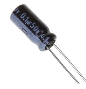
0.1µF 50V Capacitor (Pack of 50)
These 0.1µF 50V capacitors are ideal for decoupling and RC filter networks. The 50V rating gives safety margin in most 5V and 12V circuits, and they work reliably from DC to several MHz.
RC Circuits: Series and Parallel
Series RC Circuit
In a series RC circuit, the same current flows through both R and C. The voltage across R is in phase with the current, while the voltage across C lags the current by 90°. The total voltage across the series combination is the phasor sum of V_R and V_C:
V_total = √(V_R² + V_C²)
The RC time constant τ = RC defines how quickly the capacitor charges and discharges, and sets the corner frequency of the filter formed by the pair:
τ = R × C (seconds)
f_c = 1 / (2π × R × C) (Hz)
Parallel RC Circuit
In a parallel RC circuit, the same voltage appears across both R and C. The current through R is in phase with voltage, while the current through C leads voltage by 90°. The total current is the phasor sum:
I_total = √(I_R² + I_C²)
Admittance Y = G + jB_C = 1/R + jωC
|Z_parallel| = 1 / |Y| = 1 / √((1/R)² + (ωC)²)
Capacitor Applications in Filters
The frequency-dependent reactance of capacitors is exploited to build passive filters — circuits that pass certain frequencies and block others.
High-Pass RC Filter
Series capacitor + shunt resistor. The capacitor’s high reactance at low frequencies attenuates low-frequency signals, while high frequencies pass with minimal attenuation. Cut-off frequency: f_c = 1/(2πRC).
Applications: Removing DC offset from audio signals, coupling stages in amplifiers, blocking low-frequency hum.
Low-Pass RC Filter
Series resistor + shunt capacitor. At high frequencies, Xc is low and the capacitor shunts the signal to ground. At low frequencies, Xc is high and the signal passes through. Cut-off frequency: f_c = 1/(2πRC).
Applications: Smoothing power supply ripple, anti-aliasing before ADC input, removing RF interference from audio lines.
Practical Filter Design Example
Design a low-pass filter with f_c = 1 kHz to remove high-frequency noise from a sensor signal:
- Choose C = 100 nF (0.1 µF)
- R = 1 / (2π × 1000 × 100×10⁻⁹) = 1592 Ω → use 1.5kΩ or 1.8kΩ standard value
- With R = 1.5kΩ: actual f_c = 1 / (2π × 1500 × 100×10⁻⁹) = 1061 Hz ≈ 1 kHz ✓

LCR-T4 LCD Graphical Transistor Tester
Measure actual capacitance and ESR of your capacitors before using them in AC circuits. The LCR-T4 also tests inductors and transistors — perfect for verifying components match their marked values.
Practical Tips for Choosing Capacitors for AC Circuits
Match the Capacitor Type to the Frequency
- Ceramic (NP0/C0G): Best stability, ideal for precision RC filters and oscillators up to hundreds of MHz
- Ceramic (X7R): Good for bypass and decoupling at moderate frequencies (capacitance changes slightly with voltage)
- Film capacitors (polyester, polypropylene): Excellent for audio-frequency coupling and filtering — low distortion and loss
- Electrolytic: Large values (1–10,000 µF) for power supply smoothing and audio coupling, but NOT suitable above a few kHz due to high ESR and inductance
Voltage Rating
Always choose a capacitor with a voltage rating at least 2× the peak AC voltage it will see. For a 5V RMS signal, the peak is 5 × 1.414 = 7.07V, so use a 16V or 25V rated capacitor minimum.
ESR (Equivalent Series Resistance)
ESR causes power dissipation inside the capacitor. At high frequencies, ESR dominates over ideal capacitive reactance. For high-current bypass applications (like switching supply decoupling), choose low-ESR capacitors explicitly rated for that purpose.
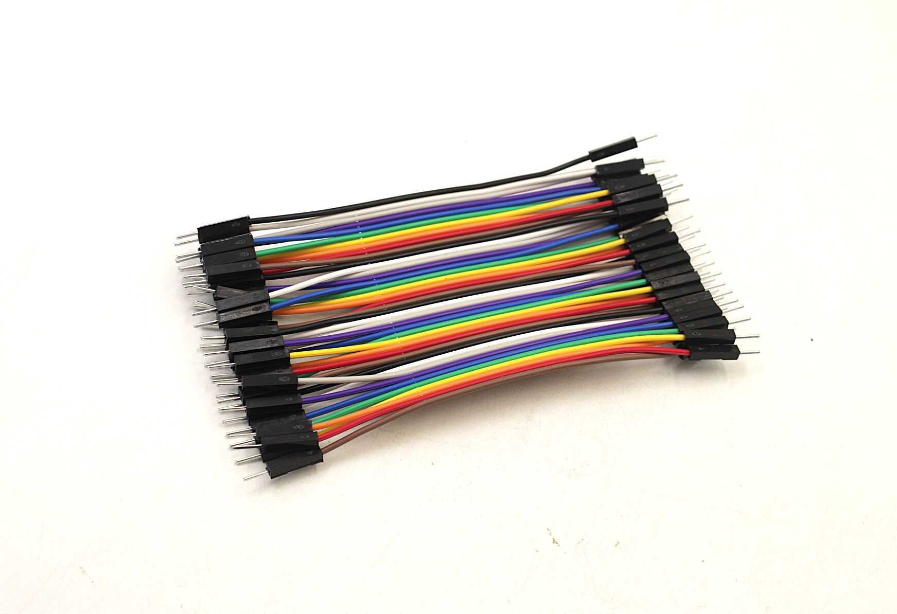
10CM Male To Male Breadboard Jumper Wires 2.54MM – 40Pcs
Build and test RC filter circuits on a breadboard with these short jumper wires. Keeping connections short reduces stray inductance and capacitance that can affect high-frequency AC measurements.
Frequently Asked Questions
Why does a capacitor block DC but allow AC to pass?
A capacitor blocks DC because, with a constant voltage, current flows only momentarily to charge the plates and then stops — the capacitor acts as an open circuit. With AC, the voltage continuously changes, causing the capacitor to continuously charge and discharge. This continuous charge/discharge allows AC current to flow through the circuit. The higher the frequency, the lower the capacitive reactance (Xc = 1/2πfC), making the capacitor increasingly transparent to AC.
What is capacitive reactance and how is it different from resistance?
Both capacitive reactance (Xc) and resistance (R) are measured in ohms and oppose current flow. However, resistance dissipates energy as heat and is independent of frequency. Capacitive reactance stores and returns energy (no heat loss) and decreases as frequency increases (Xc = 1/2πfC). Resistance causes no phase shift between voltage and current, while capacitive reactance causes current to lead voltage by 90°.
How do I calculate the cut-off frequency of an RC low-pass filter?
The cut-off frequency (also called the −3dB frequency) of an RC filter is f_c = 1 / (2π × R × C). At this frequency, the output voltage drops to 70.7% of the input (−3 dB), and the phase shift is 45°. For a 1kΩ resistor and 100nF capacitor: f_c = 1 / (2π × 1000 × 100×10⁻⁹) = 1592 Hz. Frequencies well below f_c pass with minimal attenuation; frequencies well above f_c are significantly attenuated.
Why does current lead voltage by 90° in a capacitor?
The current through a capacitor is proportional to the rate of change of voltage: i = C × dv/dt. When a sinusoidal voltage is applied, the rate of change is maximum when the sine wave crosses zero (where the slope is steepest). So current peaks when voltage is at zero and is zero when voltage is at its peak — the current waveform is a cosine while voltage is a sine, meaning current leads voltage by exactly 90°.
What is the RC time constant and how is it used?
The RC time constant τ = R × C (in seconds) determines how quickly a capacitor charges or discharges through a resistor. After one time constant, the capacitor charges to 63.2% of the final voltage. After 5τ, it reaches 99.3% (considered fully charged). The time constant is used in timer circuits (like the 555 timer), integrator/differentiator circuits, and sets the cut-off frequency of RC filters: f_c = 1/(2πτ).
Explore Capacitors and Filter Components
Shop ceramic, film, and electrolytic capacitors plus resistors for your RC filter projects. Zbotic delivers across India with fast shipping and genuine components.


Add comment