
A search rescue robot flame gas camera system can save lives in disaster zones — detecting fire, hazardous gases, and transmitting live video from places too dangerous for humans. In this comprehensive build guide, you’ll learn how to assemble a fully functional search-and-rescue robot using readily available components from Zbotic, program its sensor fusion logic, and integrate a real-time camera feed — all on a student-friendly budget.
Why Search & Rescue Robots Matter
India faces frequent industrial accidents, building collapses, and forest fires. Sending a compact robot into rubble or smoke-filled environments before human responders enter can dramatically reduce casualties. A well-built search-and-rescue robot equipped with a flame sensor, gas sensor, and camera gives the rescue team real-time situational awareness — detecting LPG leaks, carbon monoxide, or active flames within seconds.
These robots are also popular in engineering competitions like IITB Techfest, ABU Robocon, and state-level robotics olympiads. Building one teaches embedded systems, sensor integration, wireless communication, and mechanical design all at once.
Components and Hardware List
Below is the recommended bill of materials. Every item is available on Zbotic with fast pan-India shipping:
- 4WD or 2WD robot chassis (aluminium or acrylic)
- ESP32 or Arduino Mega microcontroller
- IR flame sensor module (dual or quad)
- MQ-2 or MQ-135 gas sensor module
- ESP32-CAM or USB/WiFi camera module
- L298N or L293D motor driver
- 2× DC gear motors with encoder wheels
- 11.1V 2200mAh LiPo battery or 3S Li-ion pack
- HC-SR04 ultrasonic sensor (obstacle avoidance)
- BO motors / TT motors + wheels
- Jumper wires, breadboard, PCB, screw terminals
- 3D-printed or acrylic sensor mounts

2WD Mini Round Double-Deck Smart Robot Car Chassis DIY Kit
Compact two-deck chassis with BO motors, wheels, and double-layer acrylic platform — ideal for mounting sensors and a camera module on your rescue robot.
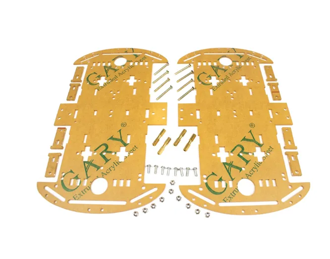
4 Wheels Car Chassis Acrylic Frame
4WD acrylic chassis for superior traction in rough terrain — essential if you plan to navigate debris or uneven rescue environments.
Chassis and Drive System Assembly
Start with the mechanical base. A two-deck chassis gives you a dedicated lower layer for motors and battery, and an upper deck for electronics — keeping everything tidy and accessible.
Step 1 — Mount the Motors
Attach BO gear motors to the four motor mounts on the chassis. Ensure the motor shafts are parallel and at equal heights. Use M3 bolts and locking nuts to prevent vibration loosening during operation on rough terrain.
Step 2 — Install Wheels and Couplings
Press the wheels onto the motor shafts. For rescue scenarios, larger-diameter rubber wheels give better grip. If you plan on tight corridors, standard 65mm wheels work well on the 2WD mini chassis.
Step 3 — Mount the Motor Driver
Fix the L298N motor driver on the upper deck. Run motor power wires from the bottom to the driver. Keep power cables short and twisted to reduce EMI interference with sensitive gas sensors.
Step 4 — Battery Placement
Mount the LiPo battery low and centred for the best centre of gravity. Use a Velcro strap so it can be quickly swapped between missions. Always include a power distribution board with a main power switch for safety.
Integrating Flame and Gas Sensors
Sensor placement is critical in a rescue robot. Flame and gas sensors must face forward and be positioned at multiple heights to cover both floor-level gas pools and elevated fire sources.
Flame Sensor (IR-based)
Connect the digital output of the IR flame sensor to a GPIO pin on the ESP32 or Arduino. The sensor detects wavelengths around 760–1100 nm (IR from flames). Orient sensors at 30–45° downward angles on each side of the robot’s front face to cover a wide arc.
int flamePin = 4;
void setup() { pinMode(flamePin, INPUT); Serial.begin(115200); }
void loop() {
  if (digitalRead(flamePin) == LOW) {
    Serial.println("FLAME DETECTED!");
    // Trigger alert / stop motors
  }
  delay(100);
}
Gas Sensor (MQ-2 / MQ-135)
The MQ-2 detects LPG, methane, smoke, and hydrogen. Connect its analog output to an ADC pin. Calibrate the baseline resistance (R0) in clean air before deployment — this is the most overlooked step that causes false alarms.
int gasPin = 34; // ADC pin on ESP32
void loop() {
  int gasValue = analogRead(gasPin);
  if (gasValue > 1500) { // threshold in ADC counts
    Serial.println("GAS ALERT!");
  }
  delay(200);
}
Mount the MQ sensor in a small 3D-printed enclosure with ventilation slots. This protects it from physical contact while allowing air circulation.
Camera System and Live Video Feed
A live video stream is what separates a useful rescue robot from a novelty project. The ESP32-CAM module is the most cost-effective solution — it has an onboard WiFi radio and supports JPEG streaming out of the box.
ESP32-CAM Setup
- Flash the
CameraWebServerexample from Arduino IDE (select AI Thinker ESP32-CAM board). - Enter your robot’s hotspot SSID and password in the sketch.
- Power the ESP32-CAM from a separate 3.3V regulator (not directly from the main ESP32 — shared power causes brownouts).
- Access the stream at
http://[ESP32-CAM-IP]/streamfrom any browser on the same network.
Camera Mounting
Mount the camera on a servo-driven pan-tilt bracket at the front of the robot. This lets the operator scan left-right and up-down remotely. Use SG90 servos for lightweight pan-tilt — they’re more than adequate for a small camera module.
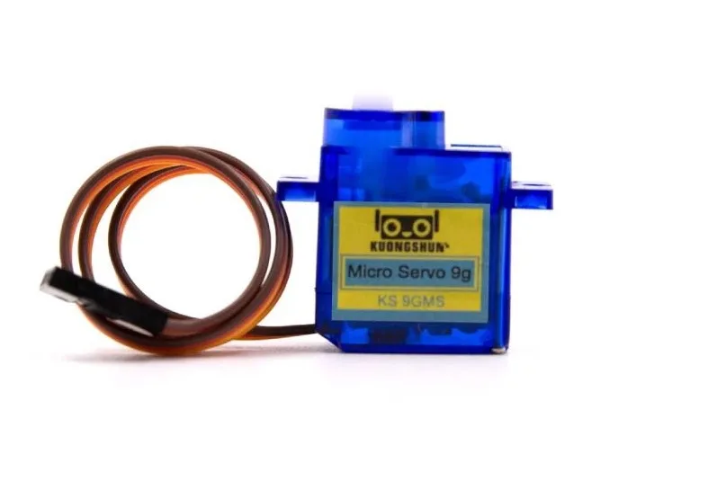
Servo SG90 9g 180 Degree
Lightweight 9g servo perfect for pan-tilt camera brackets on rescue robots. 180° rotation, standard PWM control.

Servo Mount Holder Bracket For SG90/MG90 (Pack of 2)
Aluminium servo brackets compatible with SG90 and MG90 servos — build a sturdy pan-tilt camera mount for your rescue robot.
Wiring Diagram and Connections
Here is the key connection summary for an ESP32-based rescue robot:
| Component | ESP32 Pin | Notes |
|---|---|---|
| Flame Sensor DO | GPIO 4 | Digital read |
| MQ-2 Analog Out | GPIO 34 (ADC) | 3.3V compatible |
| L298N IN1/IN2 | GPIO 25/26 | Left motor |
| L298N IN3/IN4 | GPIO 27/14 | Right motor |
| Pan Servo Signal | GPIO 18 | PWM 50Hz |
| Tilt Servo Signal | GPIO 19 | PWM 50Hz |
| HC-SR04 Trig/Echo | GPIO 5/17 | Obstacle detection |
Arduino/ESP32 Code Overview
The main control loop on the ESP32 runs four concurrent tasks using FreeRTOS:
- DriveTask — reads WebSocket commands from the operator’s phone and sets motor PWM values.
- SensorTask — polls flame and gas sensors every 200ms, sends alert packets to the operator if thresholds are exceeded.
- CameraTask — handled entirely by the ESP32-CAM on a second ESP32; streams MJPEG over HTTP.
- AlertTask — activates a buzzer and LED strip when flame or gas is detected, regardless of drive commands.
Use the AsyncWebServer library for the WebSocket server. The operator interface is a simple HTML page hosted on the ESP32 itself — no app required, works from any phone browser connected to the robot’s WiFi hotspot.
Testing and Deployment Tips
Pre-Run Checks
- Calibrate MQ-2 in clean air for at least 20 minutes before setting thresholds.
- Test flame detection with a lighter at 30 cm, 60 cm, and 1 m distances to set realistic trigger distances.
- Verify camera stream latency — should be under 500ms on a direct WiFi connection.
Competition Tips
- Add a physical emergency stop switch accessible from the outside of the chassis.
- Label sensor zones with colour-coded LEDs — red for flame, yellow for gas, green for clear.
- Use a directional buzzer to help rescuers locate the robot by sound if video is lost.
- Protect electronics with a mesh enclosure — acrylic over boards blocks heat but traps moisture.

ACEBOTT ESP32 Tank Robot Car Expansion Pack
Tank-track robot platform with ESP32 — excellent traction for rescue terrain. Expandable with sensor modules for flame and gas detection.
Frequently Asked Questions
Q: Can I use a Raspberry Pi instead of ESP32 for the rescue robot?
Yes — a Raspberry Pi 4 gives you more processing power for computer vision and SLAM. However, for beginners, ESP32 is simpler, cheaper, and adequate for flame/gas detection with camera streaming.
Q: How far can the WiFi control reach?
A direct ESP32 hotspot typically covers 30–50 metres in open air. For longer range, use a WiFi router as an access point, or switch to LoRa (up to 2 km) for command signals while keeping WiFi for video.
Q: Which is better — MQ-2 or MQ-135 for rescue robots?
MQ-2 detects LPG, methane, and smoke — the most common rescue hazards. MQ-135 is better for air quality (CO2, NH3) in industrial settings. For general rescue use, start with MQ-2.
Q: How do I power the ESP32-CAM and sensors separately?
Use an LM2596 buck converter to step down 11.1V battery to 5V for the main ESP32, then use the ESP32’s onboard 3.3V LDO for sensors. Power the ESP32-CAM from its own 5V rail via a separate small LDO to avoid brownouts.
Q: Is this robot suitable for engineering project submissions?
Absolutely. Flame + gas + camera robots are commonly accepted in IIT/NIT project exhibitions and robotics olympiads. Add an LCD display for local sensor readouts and a data logger for bonus marks.
Get all the components — chassis, sensors, servos, and more — delivered fast anywhere in India. Shop Robotics & DIY at Zbotic and start building today.


Add comment