
USB Power Bank Circuit: Build with TP4056, MT3608 & 18650
A USB power bank circuit DIY is one of the most satisfying beginner electronics projects — you end up with something genuinely useful that you built with your own hands. In this guide, we’ll show you exactly how to combine a TP4056 lithium charging module, an MT3608 boost converter, and one or more 18650 cells to create a fully functional 5V USB power bank. The total cost for a single-cell version comes to under ₹150 if you source the modules from Zbotic, making it one of the most affordable electronics projects you can build in India today.
Understanding the Three Key Modules
Before you pick up the soldering iron, it helps to understand what each module does and why you need all three.
TP4056 — The Charger
The TP4056 is a single-cell lithium-ion battery charger IC. In its common module form, it includes a Micro-USB or USB-C input, a DW01 protection IC (on the protected version), and charges the cell at up to 1A with a precise 4.2V constant-voltage end-of-charge voltage. The red LED indicates charging; blue/green indicates charge complete. The protection variant (highly recommended) also includes short-circuit and over-discharge protection.
MT3608 — The Boost Converter
An 18650 cell outputs 3.0–4.2V depending on its state of charge. USB requires exactly 5V. The MT3608 is a compact, adjustable step-up (boost) converter that takes any input from 2V to 24V and boosts it to a higher output voltage. At 5V output from a 3.7V input, it operates at roughly 85–90% efficiency. You’ll need to adjust the onboard potentiometer to set the output to exactly 5.0–5.1V before connecting any device.
18650 Cell — The Energy Store
A standard 18650 cell holds 2000–3500 mAh at 3.7V nominal, giving you 7.4–13 Wh of stored energy. At 85% boost converter efficiency, a 3000 mAh cell gives you approximately 2200–2400 mAh at 5V output — enough to charge a modern smartphone to about 60–70%.
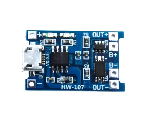
TP4056 1A Li-Ion Battery Charging Board Micro USB with Current Protection
The essential charging module for your DIY power bank. Includes over-charge, over-discharge, and short-circuit protection. Charges 18650 cells at up to 1A.
Full Circuit Schematic
The circuit is straightforward — each module connects to the next in series:
Micro USB Input
      |
   [TP4056 Module]
   IN+ ──────────────── BAT+
   IN- ──────────────── BAT-
         (charge control)
   BAT+ ─── [18650 +] ─── BAT+  (B+ / OUT+ on protected module)
   BAT- ─── [18650 -] ─── BAT-  (B- / OUT- on protected module)

   OUT+ ────────────────────────── [MT3608 IN+]
   OUT- ────────────────────────── [MT3608 GND]

   [MT3608 Module]
   OUT+ ─── [USB-A Port +5V pin]
   GND  ─── [USB-A Port GND pin]
   (Adjust pot until OUT+ reads exactly 5.0V with no load)
Important note: On the protected TP4056 module, there are separate pins for the battery (BAT+/BAT-) and the output (OUT+/OUT-). Always connect the MT3608 to the OUT pins, not the BAT pins. The OUT pins are disconnected by the protection circuit when the battery falls below 2.5V, preventing deep discharge damage.
Pass-through charging: With this basic design, you cannot charge and discharge simultaneously (the TP4056 protection circuit disconnects the load while charging on some module revisions). If you need pass-through, look for dedicated power bank management ICs like the IP5306 or use a dedicated power bank module that handles this automatically.
Components List and Where to Buy
- 1 x TP4056 1A Lithium Battery Charger Module with Protection (Micro USB or Type-C)
- 1 x MT3608 DC-DC Step-Up Boost Converter Module
- 1 x 18650 Battery (2000–3500 mAh, genuine capacity)
- 1 x 18650 Battery Holder (single cell, with wire leads)
- 1 x USB-A female port (for output)
- 1 x Slide switch or pushbutton (to disconnect the load when not in use)
- Some short lengths of 22–24 AWG wire in red and black
- Heat shrink tubing or electrical tape
- Small project box or 3D-printed enclosure
- Multimeter (for calibrating the MT3608 output voltage)

1 x 18650 Battery Holder with 18.4MM Bore Diameter – Pack of 4
Sturdy spring-contact holders that securely hold 18650 cells with reliable electrical contact. Sold in a pack of 4 — great for multi-cell power bank builds.
Step-by-Step Assembly
- Calibrate the MT3608 first (critical step): Before connecting anything to the MT3608, power it with a 3.7V source (even another battery or bench power supply) and turn the small blue potentiometer slowly clockwise until your multimeter reads exactly 5.00–5.10V on the output pins. This prevents over-voltage damage to connected devices.
- Prepare the battery holder: Solder short leads to the battery holder terminals. Use red for positive, black for negative. Keep leads short (5–8 cm).
- Connect battery to TP4056: Solder the battery holder’s positive wire to the BAT+ pad on the TP4056, and negative to BAT-. Verify the polarity — reversing this will destroy the module.
- Connect TP4056 output to MT3608 input: Solder a red wire from OUT+ on the TP4056 to IN+ on the MT3608. Solder a black wire from OUT- to GND on the MT3608.
- Add the output switch: Wire a slide switch in series with the MT3608 output positive line. This lets you turn the power bank off when not in use, preventing continuous idle discharge through the MT3608’s quiescent current.
- Wire the USB-A port: Connect the MT3608 OUT+ to the USB port’s VBUS pin (pin 1), and GND to pin 4. Leave pins 2 and 3 (data lines) unconnected — for basic charging, most devices don’t need them. For fast charging compatibility, add two 75kΩ resistors from D+ and D- to VBUS (Apple charging signature) or use a dedicated charging port controller.
- Insert the 18650 cell and test: With no load connected, switch on and verify 5V at the USB port with your multimeter. Then plug in a USB device and verify charging begins.
- House it in an enclosure: A small project box, ABS enclosure, or 3D-printed shell finishes the build. Mark the Micro USB input and USB-A output clearly.
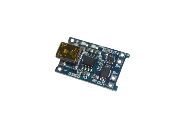
TP4056 1A Li-ion Lithium Battery Charging Module with Current Protection – Mini USB
Mini USB variant of the TP4056 charging module. Identical functionality to the Micro USB version — great as a backup or for builds with a Mini USB input preference.
Upgrading to a Multi-Cell Pack
A single 18650 cell gives you around 2000–3500 mAh — good for one phone charge. For a larger power bank (10,000 mAh equivalent), you’ll need multiple cells. Here’s how to scale up:
Parallel Configuration (same voltage, more capacity)
Wire 3 x 18650 cells in parallel: all positives together, all negatives together. This gives you 3x the capacity at the same 3.7V. The TP4056 can still charge this pack, but at 1A it will take 3x as long. For faster charging, use a dedicated multi-cell charging IC or a module that supports higher input current.
Better Option: Dedicated Power Bank Module
For builds with 2 or more cells, consider a dedicated power bank module (like those based on the IP5306 or TP5100 for 2S packs) that integrates charging, protection, boost conversion, and battery level indication in a single compact board. These also typically support pass-through charging (use while charging). The 18650 5V dual USB booster module on Zbotic does exactly this.

18650 5V 1A/2A Lithium Battery Digital Display & Charging Module, Dual USB Output
All-in-one power bank module with digital battery level display, dual USB output, and integrated boost converter. A great upgrade from the basic TP4056 + MT3608 combo for multi-cell builds.
Adding a Battery Level Display
One of the most requested upgrades is a battery level indicator — so you know when to recharge your power bank. There are a few approaches:
- Simple LED indicator: A 4-LED battery level indicator module (commonly sold for ₹30–50) connects directly to the battery terminals and displays charge state with 4 LEDs (100%, 75%, 50%, 25%). Press a button to check level.
- Voltage display module: A small 2- or 3-digit voltmeter module (0.36″ red LED) shows the exact cell voltage. Cell voltage maps directly to state of charge: 4.2V = 100%, 3.7V = ~50%, 3.0V = 0%.
- Dedicated power bank module with display: The easiest upgrade — modules like those sold on Zbotic include a digital percentage display right on the board.
Troubleshooting Common Problems
| Problem | Likely Cause | Fix |
|---|---|---|
| No output at USB port | MT3608 not calibrated or switch off | Measure output, adjust pot to 5V, check switch |
| Device not charging | Data pins not shorted or missing charging signature | Bridge D+ and D- pins on USB port |
| TP4056 red LED on permanently | Cell at very low voltage (deep discharge) or shorted | Replace cell if voltage below 2V; it’s likely dead |
| Power bank gets warm | Normal — MT3608 and TP4056 both generate heat | Ensure ventilation in enclosure; add small heatsink to MT3608 |
| Output voltage drops under load | Cell too discharged or high internal resistance | Recharge or replace the 18650 cell |
Frequently Asked Questions
What is the difference between the protected and unprotected TP4056 module?
The protected TP4056 module includes a DW01 + 8205A battery protection chip that prevents over-charge (above 4.2V), over-discharge (below 2.5V), and short-circuit on the battery output. The unprotected version only handles charging and has no discharge protection. Always use the protected version for a power bank — if the cell discharges below 2.5V, it can be permanently damaged or become dangerous.
Can I charge my iPhone with a DIY TP4056 power bank?
Yes, but iPhones require Apple’s charging signature on the D+ and D- data lines to charge at more than 0.5A. Add two voltage dividers — D+ to 2.0V and D- to 2.7V using resistors — or use a dedicated Apple charging port controller IC. Without this, the iPhone will charge very slowly (limited to USB default 0.5A) or show a “not charging” message.
How long does it take to charge the DIY power bank?
The TP4056 charges at 1A maximum. A 3000 mAh 18650 cell will take approximately 3 to 3.5 hours to charge from empty (the TP4056 transitions to trickle current near the end, extending the time slightly). You can modify the charging current by changing the PROG resistor on the TP4056 module: the factory-installed 1.2kΩ gives 1A; change to 2kΩ for 0.5A (cooler, better for cell longevity).
Why does my MT3608 get very hot?
The MT3608 generates heat proportional to the current being converted. At 1A output (5V), it’s dissipating about 0.5W — this is normal and the module should be warm to the touch but not painfully hot. If it’s very hot, check that your output voltage is correctly set to 5V (not higher), and that the input voltage is not too low (below 3V the converter works harder). Ensure good airflow in the enclosure.
Is it cheaper to build a power bank than buy one?
For a basic single-cell 3000 mAh power bank, the components cost ₹100–200 in India — comparable to the cheapest commercial options. The real value in building your own is learning, customisation (custom capacity, shape, pass-through), and the ability to replace cells when they degrade. Commercial power banks are often cheaper per mAh for large capacities, but nothing beats the satisfaction of using something you built yourself.
Build Your DIY Power Bank Today
All the modules you need — TP4056 charger boards, 18650 holders, and complete power bank modules — are available at Zbotic. Fast shipping across India, quality-tested components.


Add comment