
Wireless Charging Module Qi: Build a Charging Pad Project
Imagine placing your phone or any custom device on a pad and watching it charge — no cables, no plugging in, no worn-out connectors. Wireless charging using Qi modules has gone from premium smartphone feature to affordable DIY technology that any Indian maker can implement. In this project guide, we will build a complete Qi wireless charging pad from scratch, covering transmitter and receiver module selection, coil design, PCB layout considerations, charging efficiency, and safety — all tailored for components and budget constraints relevant to Indian hobbyists.
Understanding the Qi Wireless Charging Standard
Qi (pronounced “chee” — the Chinese word for energy flow) is the global standard for inductive wireless charging, developed by the Wireless Power Consortium (WPC). It is used in virtually all modern smartphones, earbuds cases, and smartwatches. Understanding the standard matters for your project because it determines:
- Operating frequency: Qi operates between 87–205kHz. Most baseline power (5W) implementations use ~127kHz.
- Power levels: Baseline Power Profile (BPP) delivers up to 5W. Extended Power Profile (EPP) goes up to 15W. Proprietary fast-charge protocols (Apple MagSafe, Samsung Fast Wireless) go even higher but require certified chips.
- Communication: Qi uses in-band signalling — the receiver sends data packets back to the transmitter by modulating the load. This tells the transmitter to adjust power, enables foreign object detection, and allows the receiver to report its temperature.
- Coil alignment tolerance: Standard Qi coils have ±5mm misalignment tolerance. Beyond that, efficiency drops sharply. MagSafe magnets solve this by guiding alignment mechanically.
For DIY projects, you do not need to implement the full Qi communication stack from scratch. Pre-built Qi transmitter ICs like the Texas Instruments BQ500215 or Integrated Device Technology P9222 handle all the protocol logic. For the receiver side, the BQ51013 or P9025 are popular choices that give you a clean regulated output voltage.
How Inductive Charging Works: The Physics
Wireless power transfer exploits Faraday’s law of electromagnetic induction. The transmitter coil carries a high-frequency alternating current, which creates an oscillating magnetic field. When the receiver coil is placed in this field, the changing flux induces a voltage in the receiver coil — this is the transferred power.
The efficiency of transfer depends on the coupling coefficient (k), which is a function of:
- Distance: Efficiency drops roughly as 1/d³ with coil separation. Keep the gap under 5mm for acceptable efficiency.
- Coil geometry: Larger coils with more turns have higher inductance and capture more flux, but become physically bigger.
- Alignment: Lateral misalignment beyond the coil’s inner radius drops coupling significantly.
- Frequency: Higher frequency improves coupling but increases core and switching losses. Qi’s 127kHz is a carefully chosen balance point.
Real-world Qi efficiency at 5W and 3mm gap is typically 70–80%. The remaining 20–30% is lost as heat in the transmitter MOSFETs, the coil resistance (DCR), and the receiver rectifier. This is why wireless charging pads feel warm — they are dissipating 1–2W of heat even for a 5W charge.
Components You Need for This Build
Here is the complete bill of materials for a DIY Qi wireless charging pad project:
Transmitter side:
- Qi transmitter module (pre-built with BQ500215 or equivalent IC) — available from electronics suppliers
- Transmitter coil (10µH, 40mm diameter, rated for 1.5A minimum)
- Input power supply: 5V 2A regulated adapter (USB-C PD or standard wall adapter)
- Enclosure: 3D printed or laser-cut acrylic pad
Receiver side (integrated into your custom device):
- Qi receiver module or bare receiver IC (BQ51013B or Qi 5W receiver module)
- Receiver coil (matched to transmitter, typically 10µH, 30–40mm diameter)
- Li-ion battery with protection circuit
- Optional: TP4056 charging IC as an intermediate stage for constant-current/constant-voltage control
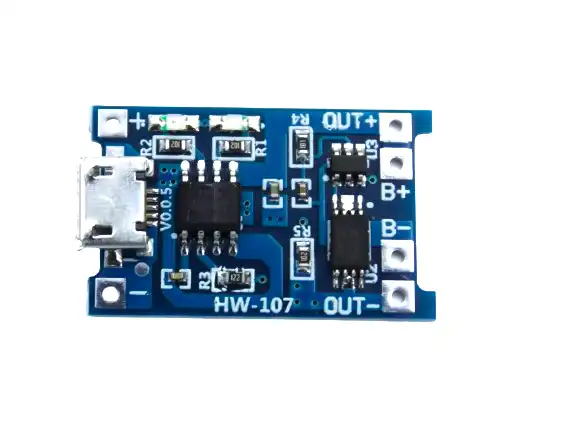
TP4056 1A Li-Ion Battery Charging Board Micro USB with Protection
Pair the TP4056 with your Qi receiver module output for clean CC/CV charging of your Li-ion battery. The built-in DW01 protection IC handles over-voltage and short-circuit protection.
Building the Transmitter Pad
The transmitter pad is the charging surface your device rests on. Follow these steps:
Step 1: Prepare the transmitter module. Most Qi transmitter modules come as a small PCB (40×40mm) with the IC already assembled. You just need to connect the coil and power supply. Solder the coil leads to the COIL1 and COIL2 pads — polarity does not matter for the coil itself as the AC current reverses direction at 127kHz.
Step 2: Connect input power. Qi transmitter ICs typically accept 5V input (some accept up to 12V for higher power levels). Connect a reliable 5V 2A USB power supply. Do not use a laptop USB port — the current capability varies and may cause the charger to repeatedly try and fail to negotiate power.
Step 3: Build the enclosure. 3D print a flat pad shell, or use a sheet of 3mm acrylic. The coil should sit flat, with no metal objects between the coil and the charging surface. Metal objects in the coil field cause eddy current heating — this is how foreign object detection (FOD) in Qi works.
Step 4: Test the transmitter. Without a receiver, the transmitter should draw only ~50–100mA (quiescent current). This is normal — it is pinging the field looking for a receiver. When you place a Qi receiver in range, current should jump to 500mA–1A depending on load. Measure input current with your multimeter; if it stays at 100mA with a receiver present, check coil connections and alignment.
Coil winding tips: If you are winding your own coil from magnet wire (Litz wire preferred for high-frequency use), aim for 15–20 turns on a 40mm former with 0.1–0.2mm wire diameter. The inductance should measure 8–12µH with an LC meter. Always measure your inductance before installing — off-spec coils cause the IC to oscillate outside the design range.
Building the Receiver Module
Step 1: Choose your receiver IC. For a 5W Qi receiver, the BQ51013B (TI) gives you a clean 5V regulated output — easy to feed into a TP4056 charger. For a more integrated approach, use a module like the CYACD module from Cypress which includes the full receiver stack.
Step 2: Position the receiver coil. The receiver coil should be as close to the device’s bottom surface as possible — maximise the coupling by minimising the distance. Stick the coil flat against the back panel with double-sided thermal tape (the thermal type helps dissipate heat from the coil).
Step 3: Connect to your battery charging circuit. The receiver IC outputs a regulated voltage (typically 5V). Connect this to your battery charger input (TP4056 module’s IN+ pin). The receiver IC handles communication with the transmitter and will regulate its output voltage to maintain constant input for your charger.
Step 4: Shield the receiver coil from metal. If your device enclosure has any metal components above the receiver coil, you need a ferrite sheet between the metal and the coil. Without ferrite shielding, the alternating field induces eddy currents in the metal, heating it up and drastically reducing charging efficiency. Ferrite sheets are thin (0.3–0.5mm) and can be cut to shape.
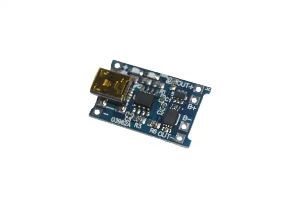
TP4056 1A Li-Ion Lithium Battery Charging Module with Protection – Mini USB
This mini USB variant of the TP4056 is ideal for compact wireless charging receiver builds where you need to fit all electronics into a small custom enclosure.
Efficiency, Heat Management and Safety
The biggest practical challenge with DIY wireless charging in India is heat management. At 5W output with 75% efficiency, 1.25W is dissipated — mostly in the transmitter coil area and the receiver IC. In a 35°C Indian summer ambient, temperatures inside an enclosure can reach 50–55°C without ventilation. At these temperatures:
- Qi receiver ICs may throttle or shut down (thermal protection typically activates at 60°C junction temperature).
- Battery cell temperature rises, reducing cycle life (Li-ion degrades 2× faster for every 10°C above 25°C).
- Plastic enclosures may warp if PLA is used (PLA softens at 60°C — use PETG or ABS for enclosures).
Thermal design guidelines:
- Add ventilation slots in your enclosure above and below the coil area.
- Use a small copper pour on both transmitter and receiver PCBs under the coil area as a heat spreader.
- Do not embed the receiver battery directly against the receiver coil — leave an air gap or place a silicone thermal pad between them.
- Mount the transmitter pad vertically (like a phone stand) rather than flat if possible — natural convection removes heat more effectively in the vertical orientation.
Safety checklist before using your build:
- Verify the transmitter draws less than 200mA with no load (checks for wiring short).
- Confirm charging stops when you place metal objects on the pad (foreign object detection working).
- Check that the transmitter surface temperature stays below 50°C after 30 minutes of charging.
- Verify the battery does not exceed 40°C cell temperature during charging.
- Test that the battery charging circuit reaches CV phase correctly (voltage at cell terminal reaches 4.19–4.21V).

1S 18650 Li-Ion BMS Charger Protection Board for 3.7V Battery
A reliable single-cell BMS protection board that works perfectly between your Qi receiver module output and your 18650 Li-ion cell. Handles all protection functions so you can focus on the wireless charging design.
Creative Applications for Wireless Charging in India
Once you understand how to build basic Qi wireless charging, the applications for Indian makers are exciting:
1. Wirelessly charged desk accessories: Embed a Qi transmitter coil under your desk surface (under a thin plywood sheet) and create a completely cable-free charging zone for your phone, earbuds, and custom devices.
2. Smart weather station: Build an outdoor weather sensor with a sealed enclosure (no charging port to let in dust or water) that charges wirelessly through a silicone gasket when docked. Critical for India’s monsoon season where open connectors fail rapidly.
3. Wireless charging for wearables: Create a custom smartwatch or fitness tracker that charges on a magnetic dock. The Qi receiver coil can be as small as 20mm diameter for wrist-worn devices.
4. Charging dock for robotics: Build an autonomous docking station for your wheeled robot. When the robot docks via IR/ultrasonic guidance, the transmitter coil aligns with the robot’s receiver coil for automatic charging — no mechanical connectors to wear out from repeated docking.
5. Public charging kiosks for events: Indian tech fests and maker faires often need charging stations. Build a multi-coil pad (4–6 coils in a single pad with multiple transmitter ICs) for a shared charging surface that multiple devices can use simultaneously.
Frequently Asked Questions
Q1: Can I use Qi wireless charging for any rechargeable battery project, or only Li-ion?
The Qi receiver output is typically 5V regulated. You can use this to charge any battery chemistry as long as you include the appropriate charger IC. For Li-ion/LiPo use a TP4056 or similar CC/CV charger. For LiFePO4 use a charger with 3.65V/cell CV setpoint. For NiMH use a ΔV detection charger. The wireless power transfer works the same regardless of the downstream battery chemistry.
Q2: How much does it cost to build a Qi wireless charging pad in India?
A basic 5W Qi transmitter module costs ₹150–300 from electronics suppliers. Receiver modules cost ₹100–200. The coils, PCB, and enclosure add another ₹200–400. Total project cost: ₹600–1,000 for a single pad and receiver — significantly cheaper than buying branded wireless chargers.
Q3: Does wireless charging through a phone case work the same way for DIY projects?
Yes, as long as the case material is non-metallic (plastic, wood, leather). Qi can charge through up to 8–10mm of non-metallic material with acceptable efficiency loss. Metal cases block the magnetic field entirely and prevent charging. For DIY enclosures, 3mm PETG or acrylic is ideal.
Q4: Will the wireless charger interfere with my other electronics?
The 127kHz magnetic field from a Qi pad can cause interference with nearby audio circuits and some sensors. Keep your Qi transmitter at least 10cm from audio amplifier input stages and RF receivers. The field falls off rapidly with distance — at 15cm, the field strength is typically below EMC limits.
Q5: How do I achieve maximum alignment accuracy in a custom docking station?
The most effective low-cost method is to use neodymium disc magnets embedded in both the dock and the device — similar to Apple MagSafe. Place 4–6 magnets in a ring pattern around the coil. The magnetic attraction guides the device into perfect alignment automatically. Use non-magnetic spacers between the magnet ring and the coil to prevent the magnets from disrupting the coil field.
Start Your Wireless Charging Project
Zbotic stocks all the battery management modules, BMS boards, and charging ICs you need to build your own wireless charging system. Get the right components delivered quickly across India and start building today.


Add comment