
You have a bag of servo motors from your last robotics project, a spare SG90 from a crashed drone, or a brand-new MG996 you want to verify before soldering it into your robot arm. How do you know if it actually works — without writing a single line of code? That is exactly what a servo tester circuit is for. This guide covers everything about servo testers: how PWM servo signals work, how to build your own servo tester with basic components, which commercial testers are worth buying, and how to safely test SG90 and MG996 servos across their full range.
How Servo PWM Signals Work
RC servo motors are controlled by PWM (Pulse Width Modulation) signals on a standard 3-wire connector: power (typically red, 4.8–6 V), ground (black or brown), and signal (yellow, orange, or white). The position of the servo horn is determined entirely by the width of the pulse on the signal wire:
- 1.0 ms pulse width → full counter-clockwise (0 degrees)
- 1.5 ms pulse width → centre position (90 degrees)
- 2.0 ms pulse width → full clockwise (180 degrees)
These pulses repeat at a frequency of 50 Hz (every 20 ms). The 20 ms period is far longer than the pulse itself — the servo reads the pulse width and drives its internal motor to match the requested position. Most standard servos accept pulses from about 0.9 ms to 2.1 ms, though some have extended ranges from 0.5 ms to 2.5 ms.
Understanding this is the key to building or choosing a servo tester. All you need is a circuit that generates a 50 Hz signal with adjustable pulse width between 1 ms and 2 ms. Everything else — the internal gearbox, feedback pot, and control circuit inside the servo — handles the rest automatically.
Why Use a Servo Tester?
A servo tester is useful in several real-world scenarios:
- Incoming quality check: Verify servos before installing them in RC aircraft, robots, or camera gimbals where removal is difficult.
- Debugging broken builds: Isolate whether a problem is in the servo, the servo controller, or the power supply.
- Centre position calibration: Find and mark the servo’s true centre before mechanically attaching servo horns.
- Endurance testing: Run a servo for 30–60 minutes and listen for grinding gears or unusual current draw before trusting it in a flying aircraft.
- Teaching aid: Demonstrate servo control principles to students without requiring a programmed microcontroller.
Commercial Servo Testers Overview
Ready-made servo testers are small, inexpensive modules available from RC hobby suppliers. They typically offer two or three operating modes:
- Manual mode: Turn a potentiometer to position the servo at any point in its range.
- Neutral mode: Outputs a fixed 1.5 ms pulse to centre the servo — useful for centring before attaching servo horns.
- Auto-sweep mode: Continuously sweeps the servo from 0 to 180 degrees and back, useful for endurance testing and finding mechanical binding.
Most commercial testers accept 4.8–6 V input and can drive 3 servos simultaneously (useful for testing complete tail assemblies or twin-servo steering setups). They are powered from the same 5 V that powers the servos, so you can run them from a USB power bank or a 4-AA battery pack. For testing in India, these are commonly available on Zbotic and similar platforms.
DIY Servo Tester with 555 Timer
You can build a perfectly functional servo tester with a 555 timer IC in astable mode, a potentiometer, and a handful of resistors and capacitors. The 555 generates a continuous square wave whose duty cycle (and therefore pulse width) is set by the pot.
Components needed
- NE555 or LM555 timer IC
- 10 kΩ potentiometer
- 1 kΩ resistor (×2)
- 10 µF electrolytic capacitor
- 5 V regulated supply (78L05 or USB power)
- 3-pin JST or servo connector
Circuit configuration
Connect the 555 in astable mode with the following values to generate a 50 Hz (20 ms period) signal:
- R1 = 1 kΩ (fixed)
- R2 = 10 kΩ potentiometer in series with 1 kΩ fixed (total R2 range: 1 kΩ to 11 kΩ)
- C = 10 µF
The frequency is approximately 1.44 / ((R1 + 2×R2) × C). By adjusting the pot, the duty cycle changes without significantly changing the frequency, giving you pulse widths from roughly 1.0 ms to 2.0 ms — the complete standard servo range.
Connect the 555 output (pin 3) directly to the servo signal wire. Power the servo from the same 5 V supply (not from the 555’s output). This simple circuit costs under ₹50 in components and works reliably with all standard 50 Hz servos.
Minimal Arduino Servo Tester
If you have an Arduino handy, a 10-line sketch turns it into a precision servo tester with a potentiometer for position control:
#include <Servo.h>

Servo testServo;
const int POT_PIN = A0;
const int SERVO_PIN = 9;

void setup() {
  testServo.attach(SERVO_PIN);
  Serial.begin(9600);
}

void loop() {
  int potVal = analogRead(POT_PIN);      // 0-1023
  int angle = map(potVal, 0, 1023, 0, 180);
  testServo.write(angle);
  Serial.println(angle);                 // watch in Serial Monitor
  delay(15);
}
Connect a 10 kΩ pot between 5V and GND with the wiper to A0. Connect the servo signal wire to pin 9, servo power to 5V (or external supply for MG996), and ground to GND. You now have a tester with real-time angle display on Serial Monitor — much more informative than a commercial tester for debugging.
To test pulse width limits beyond 0–180 degrees, replace testServo.write(angle) with testServo.writeMicroseconds(pulseWidth) and map the pot to 500–2500 µs range to explore extended servo travel.
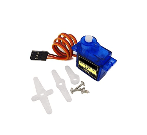
TowerPro SG90 180 Degree Rotation Servo Motor
The classic 9g micro servo for learning and prototyping. Lightweight, low current draw, works perfectly with both commercial servo testers and DIY 555 circuits.
Testing SG90 Servo Motors
The SG90 is the most popular 9g servo motor in India, used in everything from RC planes to desktop robotic arms. When testing an SG90:
- Power: 4.8 V or 5 V (USB power bank works perfectly)
- Current: 150–250 mA under load, under 10 mA at standstill when centred
- Travel: 180 degrees nominal; some units reach 190 degrees with extended pulse widths
- Speed: 0.12 s/60° at 4.8 V — should move noticeably when you sweep the pot
Common SG90 failure modes detectable with a servo tester: buzzing/humming at centre (damaged internal pot or stripped gears), partial travel only (stripped output gear), no movement but power LED on (burnt motor or driver IC), continuous rotation regardless of signal (internal pot disconnected — effectively a continuous rotation servo).
The plastic gears in SG90 are the weak point. If you feel or hear grinding during sweep testing, the servo has stripped gears and should be replaced before use in a real project. Zbotic stocks both the standard SG90 and a china-chip variant at different price points.
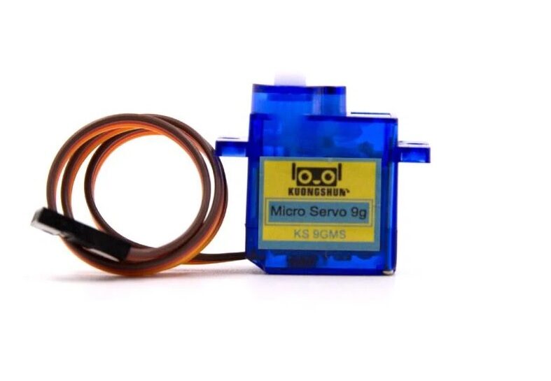
Servo SG90 9g 180 Degree (China Chip)
Budget SG90 variant — test with a servo tester before use in critical projects. Good for learning and non-structural applications where slight variation in travel is acceptable.
Testing MG996 Servo Motors
The MG996 is a heavy-duty metal-gear servo rated at 13 kg-cm torque — popular for robot arms, steering systems, and pan-tilt camera mounts. Testing requirements differ from the SG90:
- Power: 5–7.2 V; never use Arduino 5V pin — the MG996 draws up to 2.5 A under stall, far exceeding Arduino’s 500 mA regulator
- Recommended supply: 2S LiPo (7.4 V with voltage regulator to 6 V) or 4×AA alkaline (6 V)
- Travel: 180 degrees (some variants limited to 120 degrees — test to confirm)
- No-load current: 100–200 mA; stall current: up to 2.5 A — use an appropriate power supply
MG996 failures are usually in the potentiometer (servo hunts around centre and never settles) or in the control board (stops responding to signal changes). A servo tester makes these failures immediately obvious in seconds rather than requiring a full microcontroller setup.
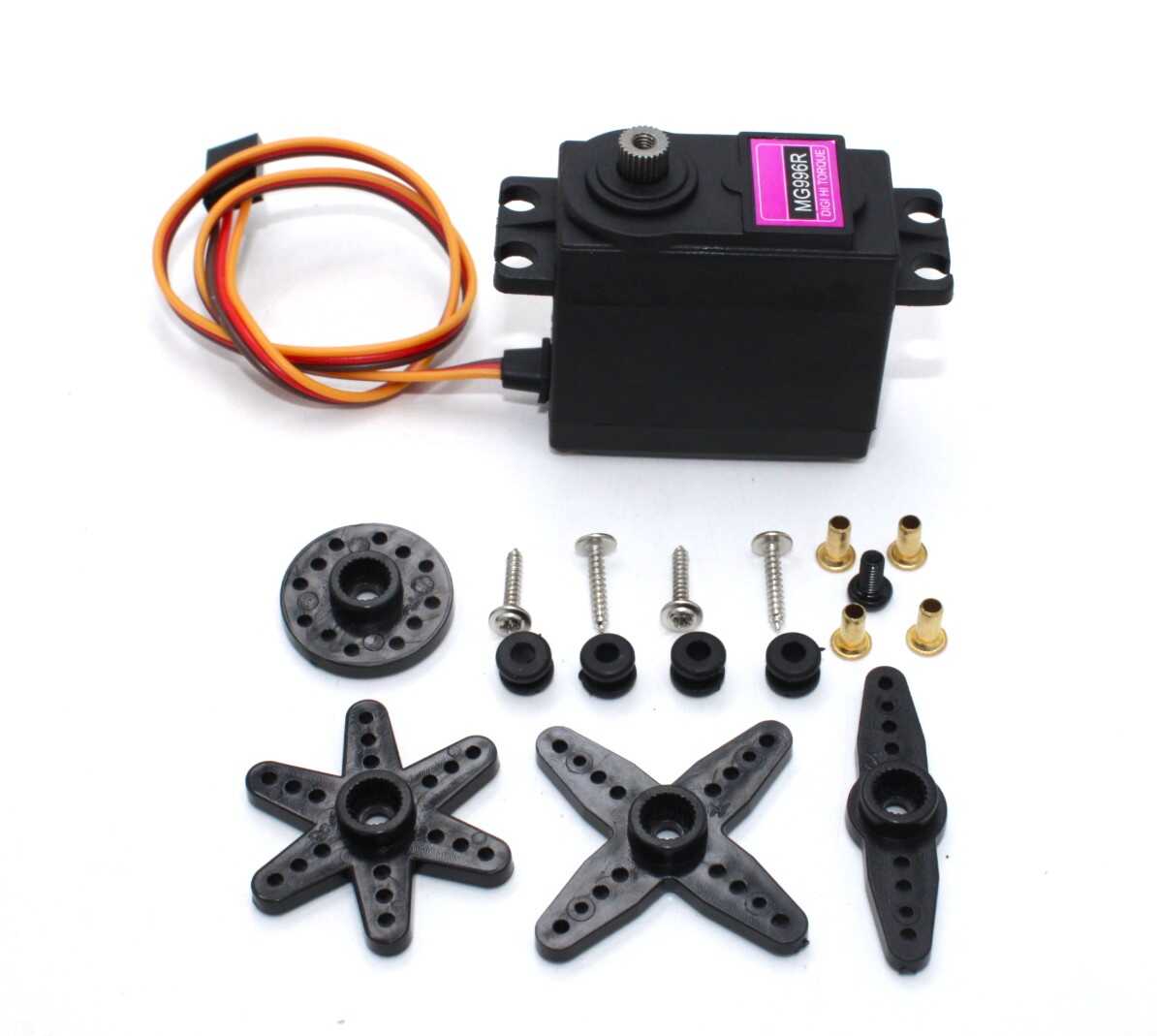
Servo MG996 13KG 180 Degree — High Quality
Metal-gear high-torque servo for robot arms and heavy steering applications. Always test with a servo tester before installing in a project — check for smooth full-range travel.
Using Extension Cables for Testing
When testing installed servos (in an RC aircraft or built robot arm), extension cables allow you to connect the servo tester without disassembling the build. Standard servo extension cables use JR or Futaba connectors — these are largely interchangeable for testing purposes, though pin order may differ.
Keep extension cables short (15–30 cm) for testing to minimise signal degradation and voltage drop. Longer cables add capacitance to the signal line, which can round the pulse edges and cause position jitter with sensitive digital servos. For permanent installations with long cable runs, use a heavier gauge (26 AWG minimum) extension cable.
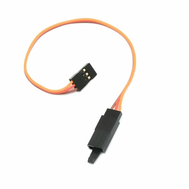
15 CM 26AWG Servo Lead Extension (JR)
Short servo extension cable for tester hookups. 26AWG wire handles MG996 currents without voltage drop issues during testing.
Diagnosing Servo Faults
| Symptom | Likely Cause | Action |
|---|---|---|
| No movement, no sound | Dead motor or power issue | Check supply voltage at servo connector |
| Buzzing, no movement | Stripped gears or stalled | Inspect gearbox; replace servo |
| Moves only part of range | Worn internal potentiometer | Replace servo or internal pot if repairable |
| Jitters constantly | Noisy power or damaged pot | Add 100 µF cap at servo power pins; replace pot |
| Runs continuously | Feedback pot disconnected | Modified for continuous rotation — use as such or replace |
| Correct position but weak | Low supply voltage or worn brushes | Increase to 6V; test current draw under load |
Practical Applications
- RC Aircraft pre-flight check: Connect a 3-channel tester across all three primary servos and sweep each axis before every flight to catch failing servos on the ground.
- Robot arm assembly: Use neutral mode (1.5 ms) to centre all servos, then attach servo horns at exactly 90 degrees before assembling the arm links.
- Camera gimbal setup: Set gimbal servos to neutral with a tester, level the camera, and mark the centre horn position before powering up the flight controller.
- Classroom demonstrations: Show students servo control principles without requiring any programming — just a tester and a potentiometer.
Frequently Asked Questions
Can I test a digital servo with the same tester as an analogue servo?
Yes. Digital servos use the same PWM protocol as analogue servos (1–2 ms pulses at 50 Hz). The difference is internal: digital servos process the pulse with a microcontroller rather than analogue circuitry, giving faster response and higher holding torque. Any servo tester that outputs correct PWM works with both types.
Why does my servo jitter on the tester but not in my Arduino project?
Jitter on a servo tester often means the tester’s power supply is noisy. The 555 timer or commercial tester oscillator can inject ripple into the servo supply. Add a 100–470 µF electrolytic capacitor directly across the servo’s power pins. Arduino sketches often power the servo from a better-filtered source, explaining the difference.
Can I use a servo tester with a continuous rotation servo?
Yes, but the behaviour is different. With a continuous rotation servo, the centre pulse (1.5 ms) means stop, pulses below 1.5 ms rotate in one direction, and above 1.5 ms rotate in the other direction. Use the tester’s pot to find the exact stop point (varies by servo) and both speed/direction extremes.
How accurate does the 555 servo tester need to be?
Standard servos tolerate considerable timing variation — a few percent in frequency does not matter. The critical measurement is pulse width: 1.0 ms for 0 degrees, 1.5 ms for 90 degrees, 2.0 ms for 180 degrees. Component tolerances in a 555 circuit typically result in less than 5% timing error, which is well within servo tolerance.
Where can I buy servo brackets and horns to complete my servo project?
Zbotic stocks servo mount brackets compatible with SG90 and MG90 servos, plus aluminium servo horns for MG995/MG996. See the bracket and horn listings under the Motors and Actuators category.
Servo Mount Holder Bracket for SG90/MG90 (Pack of 2)
ABS servo mounting brackets compatible with SG90 and MG90. Ideal for pan-tilt assemblies and robot arm joints. Pack of 2 for dual-axis applications.
Shop SG90, MG90, MG996 servos and accessories at Zbotic Motors & Actuators. GST invoice included, fast shipping across India.


Add comment