
Servo motors are among the most beginner-friendly actuators in robotics — but getting them to move to precisely the right position requires proper calibration. Incorrect calibration causes servos to grind against mechanical end-stops, skip positions, or fail to reach the true centre — problems that wear out the gearbox and make robotic joints behave erratically. This step-by-step guide covers servo motor calibration on Arduino: understanding pulse widths, finding true min/max/centre for any servo, trimming software offsets, and handling common servo models like the SG90 and MG996R.
How a Servo Motor Works
A hobby servo motor is a closed-loop position actuator. Inside its small plastic or metal case are three key components: a DC motor, a reduction gearbox (typically 100:1 to 300:1), and a position feedback potentiometer connected to the output shaft. An internal control board reads the potentiometer, compares it to the commanded position signal, and drives the DC motor to close the error.
The command interface is elegantly simple: a single PWM signal on the orange/yellow wire tells the servo where to go. The servo’s internal controller interprets the pulse width as a target position angle. The motor drives until the potentiometer matches this target, then holds still.
Three wires on a standard hobby servo:
- Brown/Black: Ground (GND)
- Red: Power supply (4.8–6 V for most hobby servos)
- Orange/Yellow/White: PWM signal input

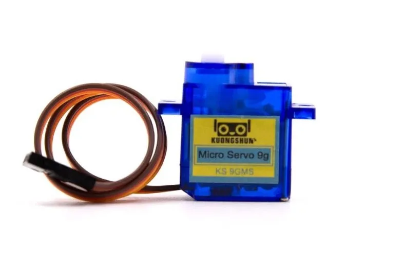
TowerPro SG90 180° Servo Motor
The most popular beginner servo in India. Lightweight 9g body, plastic gears, 180° rotation — perfect for learning servo calibration and building small pan-tilt or robotic finger mechanisms.
PWM Signal Basics: Pulse Width & Frequency
Hobby servos use a pulse-width modulated (PWM) signal operating at approximately 50 Hz (one pulse every 20 ms). The pulse width — the time the signal is HIGH during each 20 ms period — encodes the target position:
- 1000 µs (1 ms): Minimum position (typically 0°)
- 1500 µs (1.5 ms): Centre position (typically 90°)
- 2000 µs (2 ms): Maximum position (typically 180°)
However, this 1000–2000 µs range is a standard, not a law. Different servo manufacturers use slightly different ranges. The SG90 may reach its mechanical limits at 500 µs and 2500 µs. The MG996R may clip at 1000 µs and 2000 µs exactly. Calibration finds the actual range for your specific servo.
The PWM frequency (50 Hz) is also not fixed — most analogue servos require 50–60 Hz, while modern digital servos can accept up to 400 Hz for faster response. Using the wrong frequency can cause jitter or damage the servo’s internal control board.
Why Calibration Matters
Using default pulse widths without calibration causes several problems:
- Mechanical binding: If you command 0° but the servo’s mechanical minimum is actually at 700 µs (not 1000 µs), the servo gear train will grind against the internal stop, drawing stall current continuously and destroying the gearbox.
- Missed positions: A 180° servo commanded to 90° but given 1500 µs may actually sit at 95° or 85° depending on manufacturing tolerance.
- Asymmetric range: Without calibration, a servo may sweep from 0°–175° instead of the full 0°–180°, causing systematic errors in robotic arm positioning.
- Current spikes on startup: Servos jump to the commanded position on power-up. If the command is outside the true range, the spike current on startup can damage the driver and the servo simultaneously.
The Arduino Servo Library Defaults
The Arduino Servo library uses these defaults when you call servo.attach(pin):
- Minimum pulse: 544 µs
- Maximum pulse: 2400 µs
- Both values are exposed as
MIN_PULSE_WIDTHandMAX_PULSE_WIDTHdefines
When you call servo.write(angle), it maps 0–180° linearly onto 544–2400 µs. This range is intentionally wide to accommodate most servos, but it means that for a servo with a true range of 1000–2000 µs, calling servo.write(0) sends 544 µs — potentially outside the servo’s safe range.
Use the overloaded attach function to specify your calibrated values:
#include <Servo.h>
Servo myServo;

void setup() {
  // attach(pin, minPulse_µs, maxPulse_µs)
  myServo.attach(9, 1000, 2000); // calibrated values for specific servo
}
Finding True Min & Max Pulse Width
Use this systematic procedure with any servo and an Arduino:
#include <Servo.h>
Servo myServo;
int pulseWidth = 1500; // start at centre

void setup() {
  Serial.begin(9600);
  myServo.attach(9);
  myServo.writeMicroseconds(pulseWidth);
  Serial.println("Use + and - keys to adjust pulse width");
  Serial.println("Use f (fine +5µs) or c (coarse +50µs)");
}

void loop() {
  if (Serial.available()) {
    char c = Serial.read();
    if (c == '+') pulseWidth += 10;
    if (c == '-') pulseWidth -= 10;
    if (c == 'f') pulseWidth += 5;
    if (c == 'r') pulseWidth -= 5;
    pulseWidth = constrain(pulseWidth, 400, 2600);
    myServo.writeMicroseconds(pulseWidth);
    Serial.print("Pulse: "); Serial.print(pulseWidth); Serial.println(" µs");
  }
}
Procedure:
- Upload the sketch. Open Serial Monitor at 9600 baud.
- Start at 1500 µs (centre). Send
-repeatedly until the servo stops moving — this is the minimum mechanical limit. - Note the pulse width at which motion stops. Add 50 µs as your safe minimum (to avoid grinding).
- Return to 1500 µs, then send
+repeatedly until the servo stops moving. - Note the maximum pulse width, subtract 50 µs as your safe maximum.
- Record both values — these are your calibrated min and max for this servo.
Safety tip: Listen for grinding sounds. A grinding servo is hitting its mechanical end-stop. Stop adjusting immediately in that direction.
Finding & Trimming the Centre Position
The centre position (90°) is critical for any servo used in a pan-tilt mechanism, robotic joint, or steering system. Ideally, 1500 µs corresponds exactly to mechanical centre. In practice, manufacturing tolerance shifts this by ±50–100 µs.
To find true centre:
- Attach a servo horn pointing straight up or at a reference angle.
- Use the pulse-adjustment sketch to find the pulse width that positions the horn perfectly at your reference.
- Note this as your
centerPulse. Compute the offset:offset = centerPulse - 1500. - Apply this offset globally in your code — or use the calibrated attach:
servo.attach(pin, minPulse, maxPulse)with the centre reflected in your angle mapping.
For a robotic arm where perfect symmetry matters, define a calibration header file:
// servo_cal.h
#define SERVO1_MIN    620   // µs
#define SERVO1_MAX   2380   // µs
#define SERVO1_CENTER 1520  // µs (measured centre)

#define SERVO2_MIN    700
#define SERVO2_MAX   2300
#define SERVO2_CENTER 1490
Calibrating the SG90 Servo
The SG90 (and its clone, often sold as “China chip SG90”) is the most common hobby servo in India. Typical calibrated values:
| Parameter | Datasheet | Practical Range |
|---|---|---|
| Minimum pulse | 1000 µs | 500–620 µs (extends range) |
| Centre pulse | 1500 µs | 1470–1530 µs |
| Maximum pulse | 2000 µs | 2380–2500 µs (extends range) |
| Safe working range | 1000–2000 µs | 600–2400 µs |
| Supply voltage | 4.8–6 V | 4.5–6 V |
The SG90 can often exceed its stated 180° range, sweeping close to 200° with pulses from 500–2500 µs. However, use this extended range with caution — the pot may not track linearly at the extremes, and the plastic gears can strip if the shaft encounters a hard stop while at maximum pulse.
Servo SG90 9g 180 Degree (China Chip)
Budget-friendly SG90 clone with identical mechanical dimensions. Calibrate with the procedure above to get the best positioning accuracy from this widely available servo.
Calibrating the MG996R Servo
The MG996R is a metal-gear servo with much higher torque (13 kg·cm at 6 V) than the SG90. It’s widely used in robotic arms, steering mechanisms, and pan-tilt heads that carry cameras. Key differences from SG90:
| Parameter | Value |
|---|---|
| Operating voltage | 4.8–7.2 V |
| Stall torque at 6V | 13 kg·cm |
| Stall current | ~2.5 A (never power from Arduino 5V!) |
| Safe pulse range | 1000–2000 µs (stricter than SG90) |
| Dead band | 5 µs |
The MG996R is less tolerant of pulse values outside the 1000–2000 µs range than the SG90. Use the calibration procedure but stop when you first feel resistance — don’t force it further. Also note the high stall current: always power MG996R servos from a dedicated 6 V 3 A power supply, not the Arduino’s 5 V pin.

Servo MG996R 13KG 180° (High Quality)
Metal gear servo with 13 kg·cm torque — calibrate carefully with a dedicated 6V supply. Ideal for robotic arms, large pan-tilt heads, and rover steering.
Mapping Angle to Pulse Width in Code
Once calibrated, use Arduino’s map() function to convert angles to pulse widths cleanly:
#include <Servo.h>
Servo myServo;

// Calibrated values for this specific SG90 unit
const int SRV_MIN = 620;   // µs — measured minimum
const int SRV_MAX = 2380;  // µs — measured maximum
const int SRV_CTR = 1515;  // µs — measured centre

void setup() {
  myServo.attach(9, SRV_MIN, SRV_MAX);
}

// Move to angle 0–180°
void moveToAngle(int angleDeg) {
  angleDeg = constrain(angleDeg, 0, 180);
  int pulse = map(angleDeg, 0, 180, SRV_MIN, SRV_MAX);
  myServo.writeMicroseconds(pulse);
}

void loop() {
  moveToAngle(0);    delay(1000);
  moveToAngle(90);   delay(1000);
  moveToAngle(180);  delay(1000);
}
Using writeMicroseconds() directly (instead of write(angle)) gives you full control and avoids the library’s internal linear mapping which uses the default 544–2400 µs range.
Calibrating Multiple Servos
For robotic arms with 4–6 servos, individual calibration of each joint is essential. Create a calibration data structure:
struct ServoConfig {
  int pin;
  int minPulse;  // µs
  int maxPulse;  // µs
  int center;    // µs
  bool invert;   // true if mechanical mount is reversed
};

ServoConfig servos[] = {
  {3,  620, 2380, 1515, false},  // Base rotation
  {5,  700, 2300, 1490, true},   // Shoulder (inverted)
  {6,  600, 2400, 1500, false},  // Elbow
  {9,  650, 2350, 1505, false},  // Wrist pitch
  {10, 700, 2300, 1510, true},   // Wrist roll (inverted)
  {11, 720, 2280, 1500, false},  // Gripper
};
Calibrate each servo individually by testing one axis at a time. Store calibration values in EEPROM if the robot needs re-assembly, so you don’t lose calibration data on power cycle.
Power Supply Tips for Servos
- Never power servos from Arduino’s 5V pin: The Arduino Uno’s onboard regulator supplies 500 mA maximum. A single SG90 at stall draws 800 mA; an MG996R draws 2.5 A. Use a dedicated 5V or 6V power supply for servo power.
- Shared ground is mandatory: Connect the servo power supply GND to the Arduino GND. Without a common ground, the PWM signal has no reference and the servo behaves erratically.
- Decoupling capacitors: Place a 470 µF or 1000 µF electrolytic capacitor across the servo power supply rails, as close to the servo as possible. This absorbs the current spikes when the servo starts moving and prevents voltage droops that reset the Arduino.
- Multiple servos: For 4+ servos, use a dedicated servo driver board (PCA9685) which generates hardware-accurate PWM signals from I2C, freeing all Arduino timer channels and providing a higher-current 5–6 V servo rail.

Servo Mount Holder Bracket for SG90/MG90 (Pack of 2)
Securely mount your SG90 or MG90 servos in pan-tilt or robotic arm assemblies. Proper mechanical mounting is prerequisite to useful servo calibration.
Troubleshooting Common Servo Problems
- Servo jitters/vibrates at rest: PWM signal noise or marginal supply voltage. Add a 100 nF ceramic cap between signal pin and GND at the servo end. Ensure a stable regulated supply.
- Servo doesn’t reach commanded position: Pulse range mismatch. Calibrate min/max using the procedure above. Check that
attach(pin, min, max)is called with correct values. - Servo makes grinding noise: Commanded position exceeds mechanical end-stop. Immediately reduce the pulse width. Recalibrate to avoid this zone.
- Arduino resets when servo moves: Current spike on servo startup browns out the microcontroller. Add 1000 µF capacitor to servo power rail, or switch to a higher-current power supply.
- Servo position drifts over time: Internal potentiometer wear (common in heavily used SG90 servos). Replace the servo or add position feedback from an external encoder.
- Servo moves backward (inverted): Mechanical mounting requires inverted direction. Flip the pulse range:
pulse = SRV_MIN + SRV_MAX - target_pulseto mirror the position.
Frequently Asked Questions
What is the standard PWM frequency for hobby servos?
Standard analogue hobby servos require a 50 Hz PWM signal (20 ms period). Digital servos (like higher-end Futaba and Hitec models) can accept up to 400 Hz, which reduces response latency and improves holding stiffness. Using 50 Hz is safe for both types; using 400 Hz on an analogue servo may cause overheating of the internal control circuitry.
Can I use any servo with the Arduino Servo library?
Yes, provided you calibrate the min/max pulse widths correctly. The Arduino Servo library’s default range (544–2400 µs) is wide enough to accommodate most hobby servos. Use the overloaded attach(pin, min, max) form for best accuracy, or use writeMicroseconds() directly for full control.
How many servos can I connect to one Arduino Uno?
The Arduino Servo library supports up to 12 servos on the Uno (disables PWM on pins 9 and 10 when more than 8 servos are used). For reliable control of 6+ servos, use a dedicated I2C servo driver (PCA9685) which handles PWM generation in hardware and supports up to 16 channels.
My SG90 only sweeps about 160° instead of 180° — why?
The Arduino library’s default attach maps 0°–180° to 544–2400 µs, but many SG90 units don’t reach their mechanical limits until 600–620 µs and 2350–2400 µs. Recalibrate using the interactive sketch and use servo.attach(pin, yourMin, yourMax) to fix this.
What is a servo’s dead band?
Dead band is the range of pulse width change that produces no shaft movement — typically 1–10 µs for hobby servos. Below the dead band threshold, the servo’s internal controller does not detect a position error large enough to activate the motor. Cheaper servos have larger dead bands (5–10 µs), causing coarser positioning. High-quality servos have 1–2 µs dead bands for fine control.
Can I modify an SG90 for 360° continuous rotation?
Yes — remove the mechanical stop pin inside the gearbox and replace (or short) the feedback potentiometer with two equal-value resistors to create a centred reference. After modification, the servo operates as a continuous-rotation servo: 1500 µs = stop, <1500 µs = reverse, >1500 µs = forward, with speed proportional to pulse offset from centre.


Add comment