
The I2C protocol is one of the most elegant communication standards in embedded electronics. With just two wires, you can connect a microcontroller to dozens of sensors, displays, EEPROMs, and expansion modules all sharing the same bus. This guide has the I2C protocol explained from the ground up — covering address scanning, pull-up resistors, multi-device buses, and practical debugging techniques for makers using Arduino, ESP32, and similar platforms.
Table of Contents
- What is I2C?
- I2C Signal Lines: SDA and SCL
- Pull-Up Resistors: The Most Important Detail
- I2C Addressing: How Devices Are Identified
- I2C Address Scanning with Arduino
- Running Multiple I2C Devices on One Bus
- I2C Debugging: Finding and Fixing Problems
- Frequently Asked Questions
What is I2C?
I2C stands for Inter-Integrated Circuit. It was developed by Philips (now NXP Semiconductors) in 1982 and has become a universal standard for short-distance communication between ICs on a circuit board. I2C is a two-wire, half-duplex, synchronous serial protocol. The two wires carry the clock (SCL) and data (SDA) signals.
Because I2C uses an addressing scheme, a single master can communicate with up to 127 different slave devices using the same two wires — without any dedicated chip-select lines. This is I2C’s greatest advantage over SPI when you have many devices but limited GPIO pins.
I2C operates at several standardised speeds: Standard mode (100 kbps), Fast mode (400 kbps), Fast-mode Plus (1 Mbps), and High-speed mode (3.4 Mbps). For most hobby applications, 100 kbps or 400 kbps is used.
I2C is commonly used for: OLED displays, real-time clocks (DS3231), temperature sensors (BMP280, SHT31), IMUs (MPU6050), EEPROMs, GPIO expanders, and DAC/ADC chips.
I2C Signal Lines: SDA and SCL
SCL (Serial Clock Line): Generated by the master. The clock pulses synchronise all communication on the bus. In standard I2C, the master always drives SCL, though in advanced multi-master setups slaves can also hold SCL LOW (clock stretching) to signal they need more processing time.
SDA (Serial Data Line): Bidirectional data line. Both master and slave can drive SDA LOW to send data, but neither ever drives it HIGH directly. Instead, they release the line and let pull-up resistors bring it HIGH. This is the open-drain (or open-collector) bus architecture that makes I2C work.
In Arduino, I2C pins are:
- Arduino Uno: SDA = A4, SCL = A5
- Arduino Mega: SDA = 20, SCL = 21
- Arduino Nano: SDA = A4, SCL = A5
- ESP32: Default SDA = GPIO21, SCL = GPIO22 (configurable)
- ESP8266 NodeMCU: SDA = D2 (GPIO4), SCL = D1 (GPIO5)

1.3 Inch I2C/IIC 128×64 WHITE OLED Display Module 4pin
A classic I2C device for learning the protocol hands-on. This OLED uses only 2 data wires (SDA + SCL) plus power and works perfectly with the Arduino Wire library.
Pull-Up Resistors: The Most Important Detail
I2C’s open-drain architecture requires pull-up resistors on both SDA and SCL lines. Without them, the bus lines cannot rise to a HIGH state and communication is impossible. This is the most overlooked aspect of I2C for beginners.
The pull-up resistors connect SDA and SCL to the supply voltage (VCC). When no device is driving the line LOW, the resistor pulls it HIGH. When a device wants to send a 0, it drives the line LOW by connecting it to GND through its open-drain output.
How to choose pull-up resistor values:
- Standard mode (100 kbps): 4.7 kΩ to 10 kΩ is typical
- Fast mode (400 kbps): 2.2 kΩ to 4.7 kΩ
- Fast-mode Plus (1 Mbps): 1 kΩ
Too high a value and the rise time is too slow — the signal cannot reach VCC fast enough between clock pulses. Too low and you waste power and stress the output drivers. For 100 kbps, 4.7 kΩ is the most common recommendation.
Many I2C modules (especially OLED displays and sensor breakout boards) include pull-up resistors on the module PCB. If you have only one device, this is usually fine. If you are connecting multiple modules, you may end up with too many pull-ups in parallel (equivalent to a very low combined resistance), which can cause communication issues. In that case, desolder or remove the resistors from additional modules, keeping only one set.
I2C Addressing: How Devices Are Identified
Every I2C device has a 7-bit address (in standard mode), giving 128 possible addresses (0x00–0x7F). However, a few addresses are reserved, leaving 112 usable addresses. The device address is partly hardwired in the chip (fixed by the manufacturer) and partly configurable via address pins on the package.
For example, the PCF8574 GPIO expander has three address pins (A0, A1, A2). By connecting these to GND or VCC in different combinations, you can set eight different I2C addresses (0x20–0x27), allowing eight identical chips on the same bus.
The OLED SSD1306 display is commonly found at address 0x3C or 0x3D depending on a single address pin. The MPU6050 IMU is typically at 0x68 or 0x69 based on its AD0 pin.
Important: Two I2C devices with the same address cannot exist on the same bus simultaneously — they will both try to drive SDA at the same time and corrupt each other’s data. If you need two identical sensors, use a device with selectable address pins, use an I2C multiplexer (like TCA9548A), or use software I2C on different GPIO pins.
I2C Address Scanning with Arduino
Before writing device-specific code, always run an I2C scanner to confirm your device is detected and to find its address. This is the most important debugging step for any new I2C device.
Here is the classic Arduino I2C scanner sketch:
#include <Wire.h>

void setup() {
  Wire.begin();
  Serial.begin(9600);
  Serial.println("I2C Scanner");
}

void loop() {
  byte error, address;
  int nDevices = 0;

  Serial.println("Scanning...");

  for (address = 1; address < 127; address++) {
    Wire.beginTransmission(address);
    error = Wire.endTransmission();

    if (error == 0) {
      Serial.print("I2C device found at address 0x");
      if (address < 16) Serial.print("0");
      Serial.println(address, HEX);
      nDevices++;
    }
  }

  if (nDevices == 0)
    Serial.println("No I2C devices found");
  else
    Serial.println("Done.");

  delay(5000);
}
Upload this to your Arduino, open the Serial Monitor at 9600 baud, and it will scan all 127 possible addresses every 5 seconds. Each device that responds will appear with its hex address. If no devices are found, your wiring or pull-up resistors are the problem.
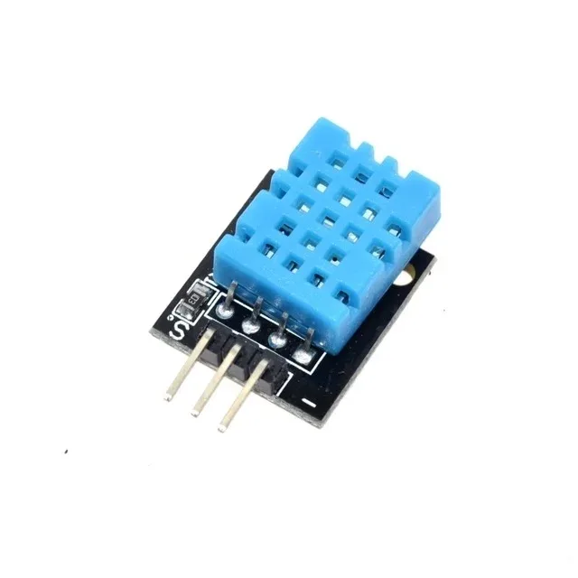
DHT11 Digital Relative Humidity and Temperature Sensor Module
While DHT11 uses a 1-wire protocol, it is a great companion sensor for I2C projects. Pair it with an I2C OLED to display live temperature and humidity readings.
Running Multiple I2C Devices on One Bus
Connecting multiple I2C devices to a single bus is straightforward — they all share SDA, SCL, and GND. As long as each device has a unique address, the master addresses them individually and ignores others.
Practical tips for a multi-device I2C bus:
- Use a central pull-up: one pair of pull-up resistors (4.7 kΩ each on SDA and SCL to VCC) shared by all devices. Remove any duplicate pull-ups on breakout boards.
- Keep wire lengths short: I2C is a low-speed bus designed for on-board communication. Long wires add capacitance and degrade signal quality. Keep total bus length under 1 metre at 100 kbps.
- Use an I2C multiplexer (TCA9548A) if you need multiple identical devices with the same address. The multiplexer gives you 8 independent I2C channels, each selectable by sending a command to the multiplexer first.
- Verify each device individually before connecting everything together. If the combined bus does not work, you will not know which device is the culprit.
I2C Debugging: Finding and Fixing Problems
I2C issues generally fall into a few categories. Here is a systematic debugging approach:
Step 1: Run the I2C scanner
If no devices show up, the problem is almost certainly wiring: SDA/SCL reversed, missing pull-ups, voltage mismatch, or broken wire. If one device shows up but another does not, the missing device may have an address conflict or a hardware fault.
Step 2: Check pull-up resistors
Use a multimeter to verify SDA and SCL are HIGH (~VCC) when the bus is idle. If they are LOW or floating, pull-ups are missing or incorrectly connected.
Step 3: Check voltage levels
A 3.3V device connected to a 5V Arduino’s I2C bus will see 5V on its SDA/SCL pins, which may damage it. Use a logic level shifter or verify the device is 5V tolerant. Most breakout boards include level shifters, but not all.
Step 4: Check for address conflicts
If the scanner finds a device at an unexpected address, check the device’s address configuration pins. It may have been set differently than expected.
Step 5: Reduce bus speed
Call Wire.setClock(50000) (50 kHz) to slow the bus. Long wires or weak pull-ups often cause problems at 100 kHz but work fine at 50 kHz. If slowing the clock fixes it, your signal integrity is the issue.
Step 6: Check for clock stretching issues
Some devices (especially slower sensors) use clock stretching to pause the master. The ESP32’s hardware I2C has a known bug with clock stretching. Use the Software I2C library on ESP32 if you encounter lock-ups with clock-stretching devices.
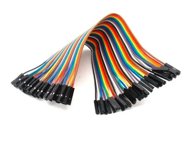
10CM Female To Female Breadboard Jumper Wires 2.54MM – 40Pcs
F-F jumper wires are ideal for connecting I2C sensor modules directly to development board female headers. A clean and reliable connection for debugging.
Frequently Asked Questions
How many devices can I connect on an I2C bus?
In 7-bit addressing mode, up to 112 devices (128 addresses minus reserved ones). In practice, bus capacitance limits are reached long before that. A well-designed bus with proper pull-ups can handle 8-16 devices without issues at standard 100 kbps speed.
What does “ACK” mean in I2C?
ACK stands for Acknowledge. After each byte sent over I2C, the receiving device pulls SDA LOW for one clock cycle to signal it received the byte correctly. If SDA stays HIGH (NACK — Not Acknowledge), the master knows the device did not respond. The Wire.endTransmission() return value in Arduino tells you whether you got an ACK (0) or NACK.
Why does my I2C device show 0x00 or 0x7F on the scanner?
Address 0x00 is the general call address and should not normally appear as a device. 0x7F is also reserved. If the scanner shows these, you may have a bus short circuit, a device in reset, or a wiring problem. Double-check your connections.
Can I use I2C over long cable runs?
Standard I2C is designed for on-board communication up to about 1 metre. For longer runs, use the PCA9600 line driver, differential I2C (LVDS), or consider switching to RS-485 for distances over a few metres.
What is the difference between I2C and IIC?
They are the same thing. IIC (Inter IC Communication) is the full form sometimes used to avoid the trademark. You will see both terms in product listings and datasheets — they always refer to the same two-wire protocol.
—
Start experimenting with I2C today! Zbotic stocks I2C OLED displays, sensors, modules, and all the jumper wires and prototyping tools you need to build your first I2C project. Shop at Zbotic.in for fast delivery across India and quality components that work right the first time.


Add comment