
Resistor Tolerance 1% vs 5%: The Complete Guide for Indian Makers
When you pick resistors for your electronics project, you’ll notice two numbers stamped on every pack: the resistance value and the tolerance percentage. Understanding resistor tolerance — 1% vs 5% — can mean the difference between a circuit that works first time and one that drifts, oscillates, or gives inaccurate readings. Whether you’re building precision sensor circuits, voltage dividers, or simple LED current limiters, this guide will tell you exactly when to pay for 1% metal film resistors and when a cheap 5% carbon film part is perfectly fine.
What Is Resistor Tolerance?
Resistor tolerance is the maximum deviation of the actual resistance from its marked (nominal) value, expressed as a percentage. A 1 kΩ resistor with 5% tolerance can have an actual resistance anywhere between 950 Ω and 1050 Ω and still be considered within specification. A 1% tolerance version of the same resistor is guaranteed to be between 990 Ω and 1010 Ω.
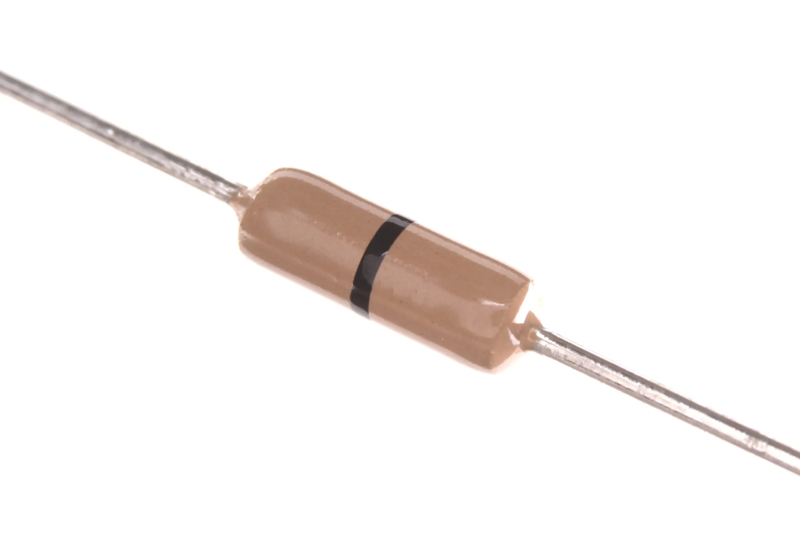
This variation arises from the manufacturing process. Resistors are produced in huge batches; the resistance of each unit depends on the thickness and composition of the resistive film deposited on the ceramic substrate. Carbon film resistors (the older, brown-coloured type) have naturally wider process variation — 5% and 10% tolerances are common and economical. Metal film resistors (blue-coloured) use a more controlled process with laser trimming of the resistive element, achieving 1% and even 0.1% tolerances routinely.
Beyond the initial tolerance, real resistors also drift over time and temperature. The temperature coefficient of resistance (TCR), measured in parts per million per degree Celsius (ppm/°C), tells you how much the resistance changes with temperature. Typical 5% carbon film resistors have TCR values of 200–500 ppm/°C, while 1% metal film resistors spec 50–100 ppm/°C. For precision applications in India’s wide temperature range (5°C to 45°C in many parts of the country), TCR can matter more than initial tolerance.
Reading Tolerance from Colour Codes
Through-hole resistors use colour band coding. The last band before the gap indicates tolerance:
| Band Colour | Tolerance | Bands | Typical Type |
|---|---|---|---|
| Silver | ±10% | 4-band | Carbon film |
| Gold | ±5% | 4-band | Carbon film |
| Brown | ±1% | 5-band | Metal film |
| Red | ±2% | 5-band | Metal film |
| Green | ±0.5% | 5-band | Metal film (precision) |
| Blue | ±0.25% | 5-band | Precision metal film |
| Violet | ±0.1% | 5-band | Precision metal film |
A quick identification tip: 4-band resistors are almost always 5% or 10% carbon film. 5-band resistors are usually 1% or better metal film. If you see a blue body, it’s almost certainly a metal film resistor with 1% tolerance.

10 Ohm 0.25W Carbon Film Resistor (Pack of 50)
Standard 5% carbon film resistor — ideal for general-purpose circuits where tight tolerance isn’t needed. Great value pack of 50 for prototyping and hobbyist projects.
1% vs 5%: Technical Comparison
Let’s put the two tolerance classes head to head across the parameters that matter most:
| Parameter | 5% Carbon Film | 1% Metal Film |
|---|---|---|
| Initial accuracy | ±5% | ±1% |
| TCR (typical) | 200–500 ppm/°C | 50–100 ppm/°C |
| Noise | Higher (carbon granule noise) | Lower (homogeneous film) |
| Long-term stability | Moderate (carbon degrades) | Excellent (metal film stable) |
| Cost (India, 1/4W) | ₹0.30–0.80 each | ₹0.80–2.00 each |
| Availability (India) | Excellent | Good (at electronics shops) |
| Body colour | Beige/tan | Blue |
| E-series (standard values) | E24 (24 values per decade) | E96 (96 values per decade) |
The E-series point is often overlooked. 5% resistors use the E24 series — 24 standard values per decade (e.g., 10, 11, 12, 13 … 82, 91). Since 5% tolerance is wide enough that adjacent E24 values don’t overlap, this series makes sense. But 1% resistors use E96, giving you 96 values per decade (10.0, 10.2, 10.5, 10.7, 11.0 … etc.), allowing you to get much closer to any desired value without complex series/parallel combinations.

1.5 Ohm 0.25W Metal Film Resistor MFR (Pack of 100)
Precision 1% metal film resistor with low TCR — ideal for precision voltage dividers, current sensing, and filter circuits. The blue body and 5-band colour code are unmistakable quality indicators.
When to Use 1% Resistors
Certain applications absolutely require tight tolerance. Here’s where you should always reach for the 1% metal film type:
1. Voltage Divider Reference Circuits
Precision voltage references and voltage dividers feeding ADC inputs need matched resistors. If you’re using a resistor divider to set a 3.3V reference from a 5V supply and both resistors are ±5%, the output voltage could range from about 2.97V to 3.63V — a 10% swing. With 1% resistors, the worst-case output is 3.24V to 3.36V — acceptable for most ADC applications.
2. Current Sensing
Current sense resistors (shunt resistors) convert current to a measurable voltage. A 0.1 Ω shunt resistor carrying 1A gives 100 mV. A 5% tolerance means the actual voltage could be 95–105 mV — a 10% current measurement error. For battery management, motor controllers, and power monitors, use 1% or better.
3. Oscillator Timing Networks
RC oscillators using 555 timers, op-amp oscillators, or discrete RC networks have frequency directly proportional to resistor values. A 5% resistor in a 1 kHz oscillator could give 950–1050 Hz. For audio applications or communication timing, 1% tolerance keeps frequency tighter.
4. Op-Amp Gain Networks
The gain of an inverting op-amp is –Rf/Rin. If both resistors are 5%, the worst-case gain error is up to 10%. For instrumentation amplifiers measuring weight, pressure, or temperature, this is unacceptable. Use 1% or precision 0.1% resistors in the gain network.
5. Wheatstone Bridge Circuits
Bridge circuits (strain gauges, load cells, temperature sensors) depend on resistor matching for accuracy. Mismatched resistors create an offset error that swamps the small signal you’re trying to measure. Always use 1% (or better, matched pairs) for bridge resistors.
6. Filter Cutoff Frequency
RC and RLC filter cutoff frequencies depend on resistor values. A 1 kHz low-pass filter with 5% resistors could have a cutoff anywhere from 952 Hz to 1052 Hz. For audio crossovers and signal conditioning, 1% gives better channel matching.
When 5% Is Perfectly Fine
Don’t overspend on precision where it doesn’t matter. 5% carbon film resistors are entirely adequate for:
LED Current Limiting
An LED current limiting resistor from 5V: you calculate 270 Ω for 10 mA. In practice, LED forward voltage varies ±0.2V and LEDs tolerate 5–20 mA without damage. A 5% 270 Ω resistor (255–284 Ω) gives 9.5–10.5 mA — perfectly fine. The LED won’t know the difference, and 5% resistors cost a fraction of 1% parts.
Pull-up and Pull-down Resistors
A 10 kΩ pull-up on an I2C line just needs to be “high enough to limit current” and “low enough for adequate signal rise time.” Whether it’s 9.5 kΩ or 10.5 kΩ makes zero practical difference. Always use 5% here.
Decoupling and Bypass Networks
Resistors in RC snubber networks, EMI filters, and power decoupling are extremely tolerant of value variation. Use 5% carbon film without hesitation.
Base Bias in Transistor Switching Circuits
If you’re driving a transistor hard into saturation (for relay drivers, LED arrays, or motor switching), the base resistor just needs to supply enough base current to saturate the transistor. A 5% variation in the base resistor is completely irrelevant — the transistor is either on or off.
0 Ohm 0.25W Carbon Film Resistor (Pack of 100)
Zero-ohm jumpers in resistor form — handy for PCB layout routing and optional population spots. No tolerance issues here! Useful for prototype and production PCBs alike.
Other Tolerances: 0.1%, 0.5%, 10%
0.1% and 0.5% Precision Resistors
These are precision metal film or wirewound resistors used in metrology, precision DACs, and medical instrumentation. They’re laser-trimmed and aged for maximum stability. In India, these are available from major distributors but at significant cost — typically ₹15–50 per resistor for 0.1%. Reserve these for applications where measurement accuracy is critical: weight scales, medical monitors, precision power supplies.
10% Tolerance
The 10% silver-band resistor is the lowest grade. You’ll rarely see these in new designs. They were common in older designs where resistors were expensive and circuit margins were wide. Today, 5% carbon film is so cheap that 10% is rarely worth buying. Avoid unless you’re restoring vintage equipment.
SMD Resistors
Surface mount resistors (0402, 0603, 0805 packages) have their tolerance marked as a 3- or 4-digit code. Standard SMD resistors are typically 1% or 5%. Interestingly, SMD 1% resistors (like the 0805 package) often cost the same as 5% SMD — so for SMD designs, just standardise on 1% throughout and simplify your BOM.
Buying Guide for India
Here’s a practical guide for sourcing resistors in India:
When to Buy Packs vs Individual Values
For general prototyping, a resistor kit (E24 series, 5%, 600–1000 pieces) costs ₹200–400 and gives you enough for months of projects. For precision work, buy specific 1% E96 values as needed. Common 1% values like 10K, 100K, 4.7K are widely stocked at Zbotic and similar electronics shops.
Quick Application Decision Guide
- LED, pull-up, transistor biasing: 5% carbon film ✓
- Voltage divider, oscillator timing: 1% metal film ✓
- Current sensing (<1% error needed): 1% or 0.5% metal film ✓
- Instrumentation, calibration: 0.1% precision ✓
- Power resistor (high wattage): Check tolerance spec separately — wirewound 5W+ resistors often have 5% or 1% ✓
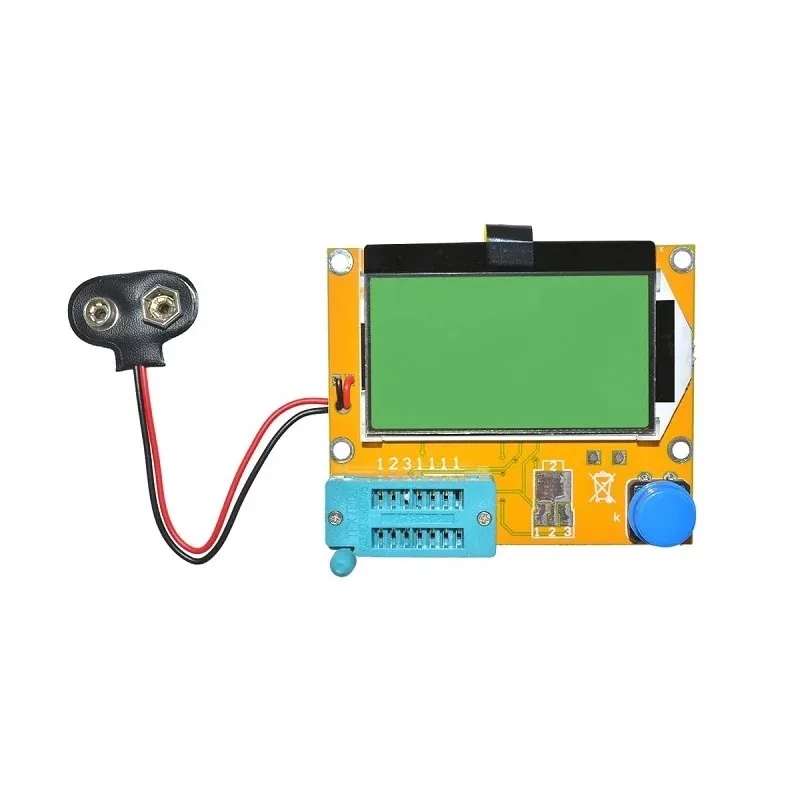
LCR-T4 Graphical Component Tester
Verify actual resistor values quickly with this LCR tester. Useful for confirming that your 1% resistors are within spec, identifying unmarked resistors, and measuring actual vs nominal values for critical circuits.
Frequently Asked Questions
Q: Can I replace a 1% resistor with a 5% resistor in an existing circuit?
It depends on the application. For LED limiting and pull-ups — yes, freely. For voltage references, op-amp gain networks, or oscillator timing — test the circuit with the actual measured value of the 5% resistor. If the measured value is close enough, it may work. But it’s risky for production designs.
Q: Are 1% resistors always more accurate than 5%?
The tolerance spec guarantees a range, not a specific value. A 5% resistor could happen to measure within 0.1% of its nominal value, while a 1% resistor will always be within 1%. For a single component, measurement is more reliable than trusting the tolerance band. For production, 1% is the only safe choice.
Q: Do resistors change value over time?
Yes, gradually. Carbon film resistors drift more than metal film. The main causes are humidity, temperature cycling, and physical stress. Metal film resistors (1%) are far more stable over years of use — another reason to use them in calibrated instruments.
Q: What does EIA-96 mean on an SMD resistor?
EIA-96 is the marking system for 1% SMD resistors. Instead of the full resistance value, it uses a 2-digit code (01–96) indicating which of the 96 E96 values it is, followed by a letter indicating the multiplier. For example, “01C” means the first E96 value (100) × 10² = 10,000 Ω = 10 kΩ.
Q: Should I just use 1% resistors for everything to keep it simple?
For SMD designs where both 1% and 5% cost the same, yes — standardise on 1% for simplicity. For through-hole prototyping, a mix makes more economic sense: use cheaper 5% carbon film for non-critical positions and 1% metal film where accuracy is needed.
Stock Up on Quality Resistors from Zbotic
Zbotic stocks a wide range of both carbon film (5%) and metal film (1%) resistors in popular values, shipped across India. Whether you need packs of 50 or 100, we have you covered for your next electronics project.


Add comment