
ESP32 interrupt handling GPIO tutorial code is one of the most searched topics among Indian hobbyists and IoT developers. When you need your ESP32 to respond instantly to a sensor trigger, button press, or external signal without constantly polling in a loop, hardware interrupts are the answer. This tutorial covers everything you need to know — from the basic theory of interrupts to writing production-ready ISR (Interrupt Service Routine) code with proper debouncing, using the Arduino IDE or ESP-IDF framework.
What Are Interrupts and Why Use Them?
In embedded programming, an interrupt is a hardware or software signal that tells the CPU to immediately pause its current task and execute a special function called an Interrupt Service Routine (ISR). Once the ISR completes, the CPU returns to whatever it was doing before.
The alternative to interrupts is polling — repeatedly checking a pin’s state inside your loop(). Polling wastes CPU cycles and can miss fast events if your loop has blocking code like delay() or long communication calls. Interrupts solve this elegantly.
Key benefits of using interrupts on ESP32:
- React to external events in microseconds, not loop-cycle delays
- Free up CPU for other tasks (critical for Wi-Fi and BLE background operations)
- Reduce power consumption in sleep modes
- Essential for time-sensitive protocols like rotary encoders and pulse counting
The ESP32 supports interrupts on all GPIO pins, which is a significant advantage over Arduino Uno (which only has 2 interrupt pins) and makes it ideal for complex IoT projects built and sold across India.
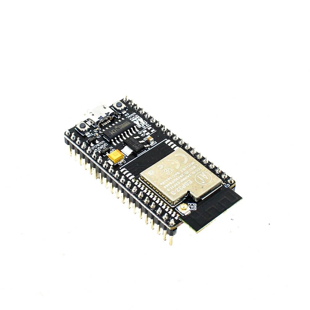
Ai Thinker NodeMCU-32S-ESP32 Development Board – IPEX Version
A reliable ESP32 development board with all GPIO pins broken out, perfect for experimenting with interrupt-driven projects. Widely used across India for IoT prototyping.
ESP32 GPIO Pins and Interrupt Support
The ESP32 has 34 programmable GPIO pins, and all of them support external interrupts. However, a few important points apply in practice:
- GPIO 34–39 are input-only; they cannot source current or drive loads, but they work perfectly as interrupt inputs from sensors.
- GPIO 6–11 are connected to the internal flash memory and should never be used as interrupt or general-purpose pins.
- GPIO 0, 2, 5, 12, 15 have boot-time constraints — avoid attaching interrupts to these if your project is sensitive to boot sequence.
- Safe, fully usable interrupt GPIO pins: 4, 13, 14, 16, 17, 18, 19, 21, 22, 23, 25, 26, 27, 32, 33, 34, 35, 36, 39.
ESP32 supports five interrupt modes (trigger types) for each GPIO:
| Mode Constant | Description |
|---|---|
RISING |
Trigger on LOW→HIGH transition |
FALLING |
Trigger on HIGH→LOW transition |
CHANGE |
Trigger on any edge (both RISING and FALLING) |
ONLOW |
Level interrupt — fires while pin is LOW (use carefully) |
ONHIGH |
Level interrupt — fires while pin is HIGH (use carefully) |
Using attachInterrupt() in Arduino IDE
The Arduino framework for ESP32 provides the familiar attachInterrupt() function. Here is the complete syntax:
attachInterrupt(digitalPinToInterrupt(pin), ISR_function, mode);Let’s build a minimal working example — a button on GPIO 27 toggles an LED on GPIO 2 using an interrupt:
const int LED_PIN = 2;
const int BUTTON_PIN = 27;

volatile bool buttonPressed = false;

void IRAM_ATTR handleButtonPress() {
  buttonPressed = true;
}

void setup() {
  Serial.begin(115200);
  pinMode(LED_PIN, OUTPUT);
  pinMode(BUTTON_PIN, INPUT_PULLUP);
  attachInterrupt(digitalPinToInterrupt(BUTTON_PIN),
                  handleButtonPress,
                  FALLING);
}

void loop() {
  if (buttonPressed) {
    buttonPressed = false;
    digitalWrite(LED_PIN, !digitalRead(LED_PIN));
    Serial.println("Button pressed - LED toggled");
  }
}
Breaking down this code:
volatile bool buttonPressed— thevolatilekeyword tells the compiler not to cache this variable in a register. This is mandatory for any variable shared between the main loop and an ISR.IRAM_ATTR— places the ISR function in IRAM (Internal RAM) instead of flash. Flash reads can be slow or blocked during cache miss; IRAM executes instantly. Always use this attribute for ISRs on ESP32.INPUT_PULLUP— activates the internal pull-up resistor. Button connects GPIO to GND, so pressing gives a FALLING edge.- The ISR only sets a flag. The actual work (Serial.println, digitalWrite) happens in
loop().
ISR Best Practices: volatile, IRAM_ATTR, and Flags
Writing good ISRs is critical for system stability. The ESP32 is a multi-core SoC running a real-time operating system (FreeRTOS), which adds extra complexity. Follow these golden rules:
Rule 1: Keep ISRs Short and Fast
Never call blocking functions inside an ISR — no Serial.print(), no delay(), no WiFi calls, no Wire (I2C) transactions. These functions are not ISR-safe and will cause a watchdog timer reset (WDT crash) or hard fault.
Rule 2: Use the Flag Pattern
Set a volatile boolean or increment a volatile uint32_t counter in the ISR. Process the action in your main loop(). This is the safest, most portable pattern:
volatile uint32_t pulseCount = 0;

void IRAM_ATTR countPulse() {
  pulseCount++;
}

// In loop():
if (pulseCount > 0) {
  noInterrupts();
  uint32_t count = pulseCount;
  pulseCount = 0;
  interrupts();
  // Process count safely here
}
Rule 3: Use noInterrupts()/interrupts() for Atomic Access
On ESP32, 32-bit variable reads/writes are atomic on a single core, but if you use 64-bit values or multi-byte structures, wrap the copy operation with portENTER_CRITICAL() / portEXIT_CRITICAL() (the FreeRTOS-safe version of noInterrupts).
portMUX_TYPE mux = portMUX_INITIALIZER_UNLOCKED;

void IRAM_ATTR myISR() {
  portENTER_CRITICAL_ISR(&mux);
  // modify shared variable
  portEXIT_CRITICAL_ISR(&mux);
}

// In main code:
portENTER_CRITICAL(&mux);
// read shared variable
portEXIT_CRITICAL(&mux);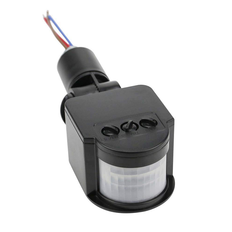
AC 220V Security PIR Human Body Motion Sensor Detector
Connect a PIR sensor output to a GPIO interrupt pin on your ESP32 to build a real-time motion detection alarm system — no polling required.
Debouncing Interrupts in ESP32
Mechanical buttons and switches suffer from “bounce” — when pressed, the contact physically bounces multiple times in 5–50 milliseconds, generating many spurious interrupt triggers instead of one. This is one of the most common issues beginners face with ESP32 GPIO interrupts.
Software debouncing inside the ISR (using millis-based check):
const unsigned long DEBOUNCE_MS = 50;
volatile unsigned long lastInterruptTime = 0;
volatile bool buttonFlag = false;

void IRAM_ATTR handleButton() {
  unsigned long now = millis();
  if (now - lastInterruptTime > DEBOUNCE_MS) {
    buttonFlag = true;
    lastInterruptTime = now;
  }
}
Note: calling millis() inside an ISR is technically safe on ESP32 Arduino (it reads a hardware timer register), but it is not recommended in very tight timing contexts. A cleaner approach uses esp_timer_get_time() which returns microseconds and is ISR-safe:
volatile int64_t lastTrigger = 0;

void IRAM_ATTR debouncedISR() {
  int64_t now = esp_timer_get_time();
  if (now - lastTrigger > 50000) { // 50ms in microseconds
    buttonFlag = true;
    lastTrigger = now;
  }
}
Hardware debouncing is more reliable: add a 0.1µF ceramic capacitor between the GPIO pin and GND, along with a 10kΩ pull-up resistor. The RC low-pass filter smooths out bounce spikes before they reach the GPIO. This is the recommended approach for production products sold in the Indian market where environmental noise can be higher.
Real-World Example: Rotary Encoder and PIR Sensor
Let’s build a real-world project: an ESP32-based security system that uses a PIR sensor interrupt to trigger an alarm, combined with a rotary encoder for menu navigation — all interrupt-driven.
#define PIR_PIN    34
#define ENC_CLK    32
#define ENC_DT     33
#define BUZZER_PIN 25

volatile bool motionDetected = false;
volatile int encoderPos = 0;
volatile int lastEncA = HIGH;

void IRAM_ATTR pirISR() {
  motionDetected = true;
}

void IRAM_ATTR encoderISR() {
  int a = digitalRead(ENC_CLK);
  int b = digitalRead(ENC_DT);
  if (a != lastEncA) {
    encoderPos += (b != a) ? 1 : -1;
    lastEncA = a;
  }
}

void setup() {
  Serial.begin(115200);
  pinMode(PIR_PIN, INPUT);
  pinMode(ENC_CLK, INPUT_PULLUP);
  pinMode(ENC_DT,  INPUT_PULLUP);
  pinMode(BUZZER_PIN, OUTPUT);

  attachInterrupt(digitalPinToInterrupt(PIR_PIN),
                  pirISR, RISING);
  attachInterrupt(digitalPinToInterrupt(ENC_CLK),
                  encoderISR, CHANGE);
}

void loop() {
  if (motionDetected) {
    motionDetected = false;
    digitalWrite(BUZZER_PIN, HIGH);
    Serial.println("ALERT: Motion Detected!");
    delay(1000);
    digitalWrite(BUZZER_PIN, LOW);
  }

  static int lastPos = 0;
  if (encoderPos != lastPos) {
    Serial.print("Encoder: "); Serial.println(encoderPos);
    lastPos = encoderPos;
  }
}
This pattern is used in many commercial IoT products shipped within India — home automation controllers, industrial counters, and smart door lock systems all rely on interrupt-driven GPIO handling like this.

30Pin ESP32 Expansion Board with Type-C USB and Micro USB
This expansion board breaks out all 30 GPIO pins of your ESP32 with labelled connectors, making it easy to prototype interrupt-driven multi-sensor projects.
ESP-IDF GPIO Interrupt Configuration
If you are working with ESP-IDF (Espressif’s official C/C++ SDK) instead of the Arduino framework, the interrupt API is slightly different but more powerful and flexible:
#include "driver/gpio.h"

#define GPIO_INPUT_PIN  GPIO_NUM_27
#define ESP_INTR_FLAG_DEFAULT 0

static QueueHandle_t gpio_evt_queue = NULL;

static void IRAM_ATTR gpio_isr_handler(void* arg) {
  uint32_t gpio_num = (uint32_t) arg;
  xQueueSendFromISR(gpio_evt_queue, &gpio_num, NULL);
}

void app_main(void) {
  gpio_config_t io_conf = {
    .intr_type    = GPIO_INTR_NEGEDGE,
    .mode         = GPIO_MODE_INPUT,
    .pin_bit_mask = (1ULL << GPIO_INPUT_PIN),
    .pull_down_en = 0,
    .pull_up_en   = 1
  };
  gpio_config(&io_conf);

  gpio_evt_queue = xQueueCreate(10, sizeof(uint32_t));

  gpio_install_isr_service(ESP_INTR_FLAG_DEFAULT);
  gpio_isr_handler_add(GPIO_INPUT_PIN,
                       gpio_isr_handler,
                       (void*) GPIO_INPUT_PIN);

  uint32_t io_num;
  while (1) {
    if (xQueueReceive(gpio_evt_queue, &io_num, portMAX_DELAY)) {
      printf("GPIO[%lu] interrupt triggeredn", io_num);
    }
  }
}
Using a FreeRTOS queue (xQueueSendFromISR) is the cleanest IDF pattern. The ISR pushes the GPIO number into the queue, and a dedicated task receives it — decoupling interrupt handling from processing completely. This approach is especially useful in multi-core ESP32 projects where you want the processing task to run on Core 1 while Core 0 handles Wi-Fi/BLE.
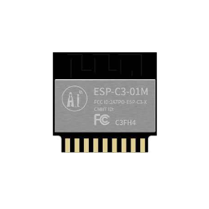
Ai Thinker ESP32-C3-01M Wi-Fi + BLE Module
A compact ESP32-C3 module ideal for interrupt-driven IoT nodes — supports GPIO interrupts and runs ESP-IDF natively at a very affordable price point in India.
Frequently Asked Questions
Can I use delay() inside an ESP32 ISR?
No, you should never call delay() inside an ISR. delay() relies on FreeRTOS tick interrupts and other background tasks, which are blocked while an ISR runs. Using delay() in an ISR will cause a watchdog timer reset and crash your ESP32. Always use the flag pattern — set a variable in the ISR and handle the delay in loop().
Why does my ESP32 reset or crash when I add an interrupt?
The most common causes are: (1) missing IRAM_ATTR on the ISR function — the function is in flash and causes a cache exception when called during a flash read; (2) calling non-ISR-safe functions like Serial, WiFi, or Wire inside the ISR; (3) a stack overflow if the ISR is too complex. Always keep ISRs minimal and use the flag/queue pattern.
How many GPIO interrupts can ESP32 handle simultaneously?
The ESP32 can handle interrupts on all GPIO pins simultaneously through a single shared GPIO interrupt service, which then dispatches to individual handlers. Practically, you can have dozens of interrupt-enabled pins active at the same time. There is a limit on the number of installed ISR service handlers (default 32), but this is rarely reached in normal projects.
What is the difference between RISING and CHANGE modes?
RISING triggers the ISR only when the pin transitions from LOW to HIGH (0V to 3.3V). FALLING triggers only on HIGH to LOW. CHANGE triggers on both transitions. For a button with INPUT_PULLUP, use FALLING for a single trigger per press. Use CHANGE for rotary encoders where you need to detect both edges to determine direction.
Is attachInterrupt() safe to call from setup() on ESP32?
Yes, attachInterrupt() is safe to call from setup() and even from within loop(). You can also remove an interrupt with detachInterrupt(digitalPinToInterrupt(pin)) at any time. This is useful for disabling interrupts temporarily during critical sections or when reconfiguring a pin’s mode.
Ready to Start Building?
Get all the ESP32 modules, sensors, and accessories you need for your interrupt-driven projects at Zbotic — India’s trusted electronics components store. Fast shipping across Mumbai, Delhi, Bangalore, Hyderabad, Pune, and all major Indian cities.


Add comment