
555 Timer IC Projects: Astable and Monostable Mode Circuits
The humble 555 timer IC is arguably the most popular integrated circuit ever made — more than a billion are produced every year. If you want to master 555 timer IC astable monostable mode circuits, you have picked the right starting point. First introduced by Signetics in 1972, the 555 remains a staple in every electronics lab, from IIT workshops in Chennai to rooftop maker spaces in Mumbai. It can generate precise timing delays, produce square waves, trigger relays, and even act as a PWM controller — all with just a handful of resistors and capacitors. Let us explore both operating modes in depth with practical formulas and project ideas.
Inside the 555 Timer: Pin Configuration and Internals
The 555 comes in an 8-pin DIP or SOP package. Understanding each pin is essential before wiring any circuit:
| Pin | Name | Function |
|---|---|---|
| 1 | GND | Ground reference |
| 2 | TRIGGER | Sets output HIGH when pulled below VCC/3 |
| 3 | OUTPUT | High or low output, can source/sink ~200 mA |
| 4 | RESET | Active-low reset; tie HIGH if unused |
| 5 | CONTROL | Modulates comparator thresholds; bypass with 10 nF to GND |
| 6 | THRESHOLD | Resets output LOW when voltage exceeds 2VCC/3 |
| 7 | DISCHARGE | Open-collector transistor; discharges timing capacitor |
| 8 | VCC | Supply voltage: 4.5 V to 16 V (NE555); 2 V to 16 V (CMOS TLC555) |
Internally, the 555 contains two voltage comparators (dividing VCC into thirds using a resistor ladder), an SR latch, a discharge transistor, and an output stage capable of sinking or sourcing up to 200 mA — enough to drive an LED, relay, or small buzzer directly without a buffer.

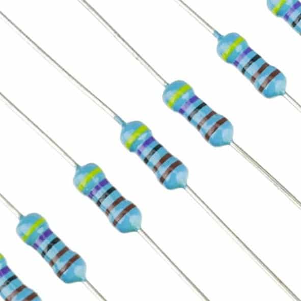
Carbon Film Resistors – Pack of 100
High-quality carbon film resistors for setting timing values in your 555 circuits. Essential passive components for every Indian electronics lab.
Astable Mode: Continuous Square Wave Generator
In astable mode, the 555 has no stable output state — it continuously oscillates between HIGH and LOW, generating a square wave. This is the most used configuration in projects requiring clocks, tones, LED blinkers, and PWM signals.
Astable Circuit Connections
- Connect pins 2 and 6 together (Threshold and Trigger both monitor the capacitor)
- Connect a resistor RA from VCC to pin 7 (Discharge)
- Connect a resistor RB from pin 7 to pins 2/6
- Connect capacitor C from pins 2/6 to GND
- Pin 4 (RESET) to VCC; 10 nF bypass capacitor on pin 5 to GND
Astable Timing Formulas
The charging time (output HIGH duration): tHIGH = 0.693 × (RA + RB) × C
The discharging time (output LOW duration): tLOW = 0.693 × RB × C
Total period: T = tHIGH + tLOW = 0.693 × (RA + 2RB) × C
Frequency: f = 1.44 / ((RA + 2RB) × C)
Duty cycle: D = (RA + RB) / (RA + 2RB)
Example: RA = 10 kΩ, RB = 10 kΩ, C = 10 µF → f = 1.44 / ((10k + 20k) × 10µ) ≈ 4.8 Hz (about 5 blinks per second — great for a heartbeat LED indicator).
Important note: In standard astable mode, duty cycle is always above 50% because RA contributes to charging but not discharging. To achieve a 50% duty cycle, use a diode in parallel with RB so the capacitor charges only through RA and discharges only through RB, then set RA = RB.

0.1/100nF Multilayer Ceramic Capacitor – Pack of 50
Perfect 100 nF decoupling and timing capacitors for 555 timer circuits. Use one on pin 5 to stabilise the control voltage and reduce noise.
Monostable Mode: One-Shot Pulse Generator
In monostable mode, the 555 has one stable output state (LOW). When it receives a trigger pulse, the output goes HIGH for a precisely defined time duration, then automatically returns to LOW. Think of it as a retriggerable or non-retriggerable one-shot timer — perfect for debouncing switches, generating fixed pulses, or creating automatic time-outs.
Monostable Circuit Connections
- Connect resistor R from VCC to pin 7, and from pin 7 to pin 6 (Threshold)
- Connect timing capacitor C from pin 6 (and 7) to GND
- Trigger input on pin 2: normally HIGH, pulse LOW to trigger
- Pin 4 (RESET) to VCC; pin 2 and pin 6 are separate (unlike astable mode)
Monostable Timing Formula
Output HIGH duration: t = 1.1 × R × C
Example: To create a 5-second delay for an auto-off light: R = 4.7 MΩ, C = 1 µF → t = 1.1 × 4,700,000 × 0.000001 ≈ 5.17 seconds.
Practical applications in India:
- Door alarm timer: Trigger with a reed switch; buzzer sounds for a fixed duration then stops automatically
- Debounce circuit: Mechanical switches bounce 1–10 ms; a 20 ms monostable output gives clean rising edge to a microcontroller
- Touch-activated relay: Combine with a touch plate — brief body capacitance on pin 2 triggers a long relay pulse
- Missing pulse detector: If an expected pulse does not arrive, the monostable output goes LOW — useful for motor stall detection
Bistable Mode: SR Flip-Flop
In bistable (or Schmitt trigger) mode, the 555 acts as an SR flip-flop with two stable states. There is no timing capacitor. Pulling pin 2 LOW sets the output HIGH; pulling pin 4 LOW resets the output LOW. This is useful for latching circuits, toggle switches, and basic memory elements in discrete logic designs.
Connections: Pin 5 decoupled with 10 nF to GND; pin 6 connected to GND or left open (through a pull-up resistor); pin 2 and pin 4 have pull-up resistors to VCC. Each button momentarily pulls the respective pin LOW.
Practical 555 Timer Project Ideas
1. LED Blinker (Astable)
The simplest project: RA = 4.7 kΩ, RB = 4.7 kΩ, C = 100 µF gives approximately 1 Hz blink rate. Connect an LED with a 470 Ω series resistor between pin 3 and GND. The 555 can source/sink enough current for a single LED directly.
2. Adjustable PWM Fan Speed Controller (Astable)
Replace RA with a 10 kΩ potentiometer. This changes the duty cycle and thus the average power to a small DC fan or motor. Frequency around 1–10 kHz avoids audible whine. Add a MOSFET or transistor on the output to handle fan current above 200 mA.
3. Automatic Night Light Timer (Monostable)
Trigger with an LDR (Light Dependent Resistor) voltage divider connected to pin 2. When lights go off, the LDR voltage drops, triggering the 555. The monostable output drives a relay for a set duration (say 30 minutes), then shuts off. Combine with the 12V 2A power supply for a complete standalone unit.
4. Morse Code Tone Generator (Astable + Switch)
Set the astable frequency to 800 Hz (audio tone). Connect the output to a piezo buzzer. Use a push button in series with pin 4 (RESET) — pressing the button enables the tone, releasing stops it. Practice Morse code signalling with minimal components.
5. Soil Moisture Indicator (Astable Frequency Shift)
Use two soil probes as a variable resistor for RB. Wet soil has lower resistance, increasing the frequency and pitch of a connected buzzer. Dry soil gives a slow, low-pitched beep. A completely practical and zero-microcontroller Indian agriculture project.
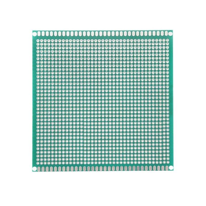
10×10 cm Universal PCB Prototype Board – Single Sided
Move your 555 timer circuit off the breadboard onto a neat prototype board. 2.54 mm pitch holes fit standard DIP ICs and resistors perfectly.
Circuit Building Tips and Common Mistakes
Always bypass pin 5: Connect a 10 nF ceramic capacitor between pin 5 (Control Voltage) and GND on every 555 circuit, even if you are not using pin 5 for modulation. This filters power supply noise from the internal comparators and improves timing accuracy.
Power supply decoupling: Add a 100 nF capacitor close to pin 8 (VCC) to GND. Switch-mode power supplies introduce high-frequency noise that can cause erratic 555 behaviour.
Trigger pulse width: In monostable mode, the trigger pulse on pin 2 must be shorter than the desired output pulse. If the trigger stays LOW longer than t, the output will stay HIGH for as long as pin 2 is LOW plus the timing period — causing longer-than-expected pulses.
Electrolytic capacitor polarity: When using large timing capacitors (10 µF and above, usually electrolytic), ensure the positive terminal connects to pin 6 and the negative to GND. Reversed polarity can damage the capacitor or cause erratic timing.
CMOS 555 for low-voltage/low-power: The standard NE555 draws 3–6 mA and works from 4.5–16 V. The TLC555 (CMOS variant) works from 2–15 V, draws only 200 µA, and has rail-to-rail output. Use the CMOS version for battery-powered or 3.3 V microcontroller projects.
1/4W Metal Film Resistors – Pack of 100
High-precision 1% tolerance metal film resistors for accurate 555 timer timing. Better temperature stability than carbon film for long-duration timing circuits.
Frequently Asked Questions
What is the maximum frequency achievable with a 555 timer?
The standard NE555 can reliably oscillate up to about 500 kHz in astable mode. Above that, the internal transistor switching times limit accuracy. CMOS versions like the TLC555 or LMC555 can operate higher but still max out around 1–2 MHz. For higher frequencies, dedicated timer ICs or oscillators are preferred.
Why does my 555 circuit frequency drift with temperature?
Timing depends on R × C values, and resistors have temperature coefficients — carbon film resistors drift more than metal film. For temperature-stable timing, use 1% metal film resistors. Also ensure a good quality capacitor (COG/NP0 ceramic for small values, or film capacitors for larger values) rather than cheap electrolytic or X7R ceramic caps.
Can I use a 555 timer with a 3.3V Arduino or ESP32?
The standard NE555 requires a minimum of 4.5 V to operate reliably. Use the CMOS TLC555 (minimum 2 V) for 3.3 V systems. Additionally, the output of a 3.3 V CMOS 555 will be 3.3 V HIGH — compatible with ESP32 and STM32 GPIO inputs.
What is the difference between 555 and 556 timer IC?
The 556 is simply two independent 555 timers in a single 14-pin DIP package. This saves board space when you need two timing functions in one circuit — such as an astable oscillator and a monostable delay running simultaneously.
How accurate is 555 timer timing?
Typical accuracy is ±1% over a stable temperature and supply voltage. Real-world circuits often see ±5–10% variation due to component tolerances and temperature drift. For precision timing (seconds to minutes range), a real-time clock (RTC) IC like DS3231 is more appropriate. For sub-millisecond pulses, a microcontroller hardware timer is more accurate.
Build Your First 555 Timer Circuit Today
The 555 timer is the perfect introduction to analogue electronics — inexpensive, robust, and incredibly versatile. Get your components from Zbotic and start experimenting. We stock resistors, capacitors, prototype boards, and all the jumper wires you need for breadboard prototyping.


Add comment