
Building a quadruped walking robot is one of the most rewarding projects a maker, student, or robotics enthusiast can undertake. Unlike wheeled robots, a 3D printed quadruped mimics the fluid motion of animals — four legs, coordinated gaits, and impressive terrain adaptability. Thanks to affordable 3D printing technology and widely available servo motors, this project is now very much achievable in India, even on a modest budget.
In this comprehensive guide, we walk you through everything: the mechanical design concepts, the parts you need, how to print them, how to assemble the robot, and how to program basic walking gaits. Whether you are a college student working on a final-year project or a hobbyist who wants to go beyond RC cars, this guide has you covered.
What Is a Quadruped Robot?
A quadruped robot is a legged machine with four limbs that can walk, trot, or even run across various surfaces. The word comes from the Latin quadrupes, meaning four-footed. In robotics, quadrupeds are studied extensively because they can navigate uneven terrain, climb over small obstacles, and recover from disturbances far better than wheeled or tracked robots.
Famous research quadrupeds include Boston Dynamics’ Spot and MIT’s Cheetah. But the principles behind them — inverse kinematics, gait planning, servo coordination — can be implemented in a compact, 3D-printed robot that fits on your desk.
A typical small quadruped uses 12 servo motors: 3 per leg (hip yaw, hip pitch, and knee). This gives each leg 3 degrees of freedom (DOF), enabling realistic walking motion. Some simpler beginner designs use 8 servos (2 DOF per leg) which are easier to program but have limited terrain handling.
Why 3D Print Your Robot?
3D printing transforms what used to be an expensive, months-long machining project into a weekend build. Here are the core advantages:
- Cost: A full set of 3D printed structural parts for a small quadruped costs under ₹500–₹800 in filament. The same parts machined from aluminium would cost tens of thousands of rupees.
- Iteration Speed: If a bracket is too weak or a servo mount does not fit, you redesign and reprint in hours — not weeks.
- Customization: Adjust leg length, body width, or mounting geometry to suit your servo brand without ordering custom parts.
- Community Designs: Open-source designs like SpotMicro, Petoi Bittle-inspired designs, and many Thingiverse/Printables uploads are ready to print.
The key requirement is a printer that can produce dimensionally accurate, strong parts. For a load-bearing robot body, PLA or PETG is recommended over cheap unbranded filament, because consistent diameter and composition directly affect how well servo horns and bearings fit.
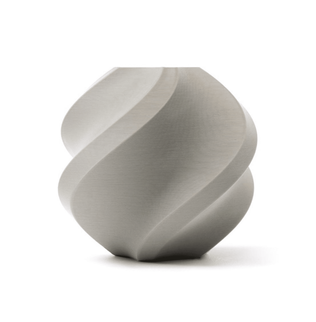
Bambu Lab PLA 3D Printer Filament – Grey 1.75mm with Reusable Spool
High-precision Bambu Lab PLA with tight diameter tolerance — ideal for robot structural parts where servo horn fit and bearing seats must be dimensionally exact.
Parts List and Bill of Materials
Here is a complete BOM for a 12-DOF 3D printed quadruped (SpotMicro-style or similar):
Mechanical Parts (3D Printed)
- Body shell (top and bottom halves)
- 4x upper leg (thigh) links
- 4x lower leg (shin/tibia) links
- 4x foot/toe pieces (TPU recommended for grip)
- 4x shoulder/hip joint brackets
- Servo horn adapters (3D printed or metal, as required)
Electronics
- 12x MG996R or DS3225 servo motors (metal gear preferred)
- 1x Raspberry Pi 4 (2GB) or Arduino Mega + PCA9685 servo driver board
- 1x 16-channel PCA9685 I2C PWM servo driver
- 1x 7.4V 3000mAh LiPo battery pack
- 1x 5V 5A BEC/UBEC power module for logic power
- MPU6050 IMU (optional, for balance control)
- HC-SR04 ultrasonic sensor (optional, for obstacle detection)
Hardware
- M2, M3 screws and nuts assortment
- Servo horns (usually included with servos)
- 608 bearings (optional, for smoother hip joints)
- Brass heat-set inserts M3 (for clean threaded holes in PLA)
Estimated Cost (India, 2026)
| Component | Approx. Cost |
|---|---|
| 12x MG996R Servos | ₹2,400–₹3,600 |
| Raspberry Pi 4 / Arduino Mega | ₹3,500 / ₹900 |
| PCA9685 servo driver | ₹180–₹300 |
| LiPo battery + charger | ₹1,200–₹1,800 |
| PLA/PETG filament (~400g) | ₹400–₹700 |
| Screws, inserts, misc hardware | ₹200–₹400 |
| Total (Arduino build) | ~₹5,000–₹7,000 |
Mechanical Design Concepts
Before printing, understanding a few mechanical principles will save you from rebuilding your robot from scratch.
Leg Geometry: The 3-DOF Leg
Each leg has three joints: the coxa (hip abduction/adduction), the femur (hip flexion/extension), and the tibia (knee flexion). This arrangement is borrowed directly from insect anatomy and is the standard in hobby quadrupeds.
- Coxa servo: Rotates the entire leg left/right. Typically a smaller servo (MG90S class).
- Femur servo: Raises and lowers the thigh. Needs medium torque.
- Tibia servo: Bends the knee. Needs the most torque as it carries impact during foot strike.
Link Lengths
Standard desktop quadrupeds use femur and tibia links of 80–100 mm each, with a coxa offset of 30–50 mm. Longer legs increase stride length and speed but reduce stability. Shorter legs are more stable but slower. For a first build, stick to the link lengths in the design files you choose.
Body Width and Leg Spacing
A wider body places the legs further apart, improving lateral stability. Most SpotMicro-derived designs have a body 100–120 mm wide and 220–260 mm long. These dimensions work well with a 3S LiPo and a Raspberry Pi 4 mounted internally.
3D Printing Tips for Robot Parts
Robot structural parts have different printing requirements than decorative prints. Follow these guidelines:
- Layer height: Use 0.2 mm for structural parts. Avoid 0.3 mm on leg links — thicker layers reduce inter-layer adhesion and the parts may snap under load.
- Infill: 40–60% for body panels, 60–80% for leg links and joint brackets. Gyroid or honeycomb infill offers the best strength-to-weight ratio.
- Perimeters/walls: Use at least 4 perimeter loops on all structural parts. For servo mounts, 5–6 loops prevent the mount from cracking when the servo is torqued.
- Material: PLA works for indoor, demo robots. PETG is better if the robot will be outdoors or in a warm workshop. Avoid ABS unless you have an enclosure — warping on flat body panels is a real risk.
- Supports: Most well-designed quadruped STL files include print-in-place supports or are oriented to minimize support use. Use tree supports if needed.
- Tolerances: Print a servo horn test piece first. Your servo horn should slide in with slight resistance, not be loose. Typical interference fit is 0.1–0.2 mm tighter than the measured servo horn diameter.

eSUN PETG 1.75mm 3D Printing Filament 1kg – Clear
PETG offers excellent layer adhesion and toughness — perfect for robot leg links that must flex slightly under load without snapping.
Step-by-Step Assembly Guide
Step 1: Install Heat-Set Inserts
Using a soldering iron set to around 200–220°C, press M3 brass heat-set inserts into all threaded holes while the plastic is warm. This prevents threads from stripping when you repeatedly assemble and disassemble the robot during debugging.
Step 2: Mount Coxa Servos
Attach the coxa (shoulder) servo into its bracket and secure with M2 or M3 screws. Position the servo horn at 90° (center of travel) before fastening. This ensures the leg has equal range of motion in both directions. Use a servo tester or a quick sketch to centre all 12 servos before assembly.
Step 3: Assemble the Leg Links
Join the femur link to the coxa servo horn. Then attach the tibia link to the femur servo. Double-check that the knee servo is centred at 90°. A common mistake is assembling the leg with one servo at an extreme position — this wastes half the range of motion and makes gait tuning impossible.
Step 4: Assemble All Four Legs
Build all four legs identically before mounting them to the body. Lay them out and verify they all look the same and can be folded/extended to the same positions. Small inconsistencies here cause limping gaits later.
Step 5: Mount Legs to the Body
Attach each leg assembly to the body’s shoulder bracket. Route servo cables through the body shell’s cable channels. Most designs have neat routing slots — use them. Cable chaos is the number-one cause of jammed joints.
Step 6: Install Electronics
Mount the PCA9685 board, microcontroller, and BEC inside the body. Solder power leads carefully — the 12 servos at stall can draw 6–8A peak. Use at least 20 AWG wire for power rails. Connect all servo signal wires to the PCA9685 channels in a consistent order (e.g., front-left: channels 0-2, front-right: 3-5, rear-left: 6-8, rear-right: 9-11).
Step 7: First Power-On Test
Before installing the battery, verify there are no shorts with a multimeter. Then connect the LiPo, power on, and immediately check that no servos are straining. All servos should be relaxed at their centred positions.
Electronics and Wiring
The brains of the robot can be either a Raspberry Pi 4 (for ROS-based advanced control) or an Arduino Mega + PCA9685 (for simpler PWM control). Here is the connection summary:
- PCA9685 → Microcontroller: SDA → SDA, SCL → SCL, VCC → 3.3V (RPi) or 5V (Arduino), GND → GND
- PCA9685 V+: Connect to the 5V regulated output from your BEC (not the LiPo directly)
- Servo power: All 12 servo power leads share a common 5V/6V bus from the BEC
- LiPo → BEC: 7.4V in, 5V/5A out for servos; a second 5V/3A BEC can power the Pi separately
Important: Never power the Raspberry Pi from the same BEC as the servos. Servo switching noise causes Pi crashes and SD card corruption. Always use separate regulators.
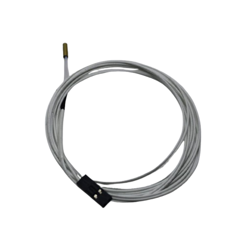
100k NTC Thermistor With Copper Tip for MK8 Extruder
Keep your printer in peak condition for long robot print jobs — a reliable thermistor ensures accurate temperature control during extended prints.
Programming the Walking Gait
The gait is the sequence of leg movements that produces forward motion. For a quadruped, the most common gait for beginners is the crawl gait (also called the static walk), where only one leg moves at a time and the body’s center of mass always remains within the support triangle of the three grounded legs.
Inverse Kinematics (IK) Basics
Rather than controlling servo angles directly, most quadruped code uses inverse kinematics to control the 3D position of each foot. You specify where you want the foot (X, Y, Z), and the IK solver calculates the required femur and tibia angles.
For a simple 2D IK (ignoring coxa rotation):
L = sqrt(x*x + z*z)  // leg reach
angle_knee = acos((L^2 - femur^2 - tibia^2) / (2 * femur * tibia))
angle_hip = atan2(z, x) - atan2(tibia * sin(angle_knee), femur + tibia * cos(angle_knee))
Crawl Gait Sequence
For a 4-leg crawl, the typical sequence is:
- Shift body weight diagonally over the three supporting legs
- Lift free leg, move it forward (step)
- Place free leg down
- Push body forward
- Repeat for next leg in sequence: FL → RR → FR → RL
Recommended Libraries
- Arduino: Adafruit PWM Servo Driver library for PCA9685. Implement IK yourself or use the Hexapod Arduino library adapted for 4 legs.
- Raspberry Pi / Python:
adafruit-circuitpython-pca9685+ custom IK, or the SpotMicro ROS package which handles everything from gait planning to IMU feedback.
Common Problems and Fixes
| Problem | Cause | Fix |
|---|---|---|
| Robot lists to one side | Servo zero offset not calibrated | Trim individual servo offsets in code until stance is level |
| Legs shake / jitter | Power noise or low BEC current | Add 1000µF capacitor on servo power bus; upgrade BEC |
| Robot falls forward while walking | Weight not shifted before stepping | Increase body shift distance in gait code before lifting each leg |
| Leg bracket cracked | Insufficient perimeters/infill | Reprint at 80% infill, 5 perimeters; consider PETG |
| Servo overheating | Stall torque exceeded; stance too low | Raise stand height to reduce knee load; use DS3225 high-torque servos |
Frequently Asked Questions
How long does it take to build a 3D printed quadruped?
Printing all parts takes 15–25 hours total. Assembly takes 4–8 hours. Getting the gait working correctly (calibration and programming) takes another 4–10 hours. Budget a full weekend for the hardware and another for the software. Expect the first real walking attempt within 3–4 days of starting the project.
Which is better for this project — Arduino or Raspberry Pi?
For a beginner, Arduino Mega + PCA9685 is easier to start with: no OS, no Wi-Fi setup, instant boot, and simple C++ code. Raspberry Pi unlocks ROS, computer vision, remote control over Wi-Fi, and more advanced gait algorithms. A common approach is to start with Arduino, get the robot walking, then migrate to Pi for advanced features.
Can I use PLA filament for the entire robot?
Yes, PLA works well for an indoor robot. Use a high-quality brand with tight diameter tolerance. Standard cheap filament can vary by ±0.1 mm in diameter, causing under-extrusion mid-print and weak layers. For outdoor or competition use, PETG or ASA is more durable. Avoid ABS unless you have an enclosure — it warps easily on flat body panels.
What is the maximum weight a small quadruped can carry?
A 12-DOF desktop quadruped using MG996R servos (11 kg·cm torque) can typically carry 200–400g of payload on flat ground. The robot itself weighs around 800g–1.2kg. Attempting to carry more causes servo stall, overheating, and eventual gear stripping.
Where can I find free STL files for quadruped robots?
The best sources are Printables.com, Thingiverse.com, and GitHub. Search for SpotMicro, Fenrir quadruped, or Mini Pupper. Many are fully open-source with assembly instructions. Choose designs that have active communities (recent comments, update history) as they are more likely to have fixes for known issues.
Do I need any special tools beyond the 3D printer?
Yes. A soldering iron (for heat-set inserts and electronics), a multimeter, a servo tester (to centre servos before assembly), M2/M3 hex keys, and needle-nose pliers. A LiPo charger with balance charging capability is mandatory for battery safety. Total additional tool cost is typically under ₹1,500 if you already have the printer.
Ready to Start Your Quadruped Build?
All the filament, nozzles, hotend parts, and printer accessories you need are available at Zbotic. Shop quality components trusted by Indian makers and robotics students across the country.


Add comment