
Table of Contents
- Introduction: Why Control Speed and Direction?
- Understanding the H-Bridge Circuit
- Components You Need
- Circuit Diagram and Wiring
- PWM Speed Control Explained
- Arduino Code: Speed and Direction Control
- Adding a Potentiometer for Manual Speed Control
- Current Limiting and Motor Protection
- Freewheeling Diodes and Why They Matter
- Troubleshooting Common Issues
- Recommended Products
- Frequently Asked Questions
- Conclusion
Introduction: Why Control Speed and Direction?
Controlling both the speed and rotational direction of a 12 V DC motor is a fundamental skill in electronics and robotics. Whether you’re building a wheeled robot, an automated conveyor, a window blind controller, or an electric vehicle prototype, you need precise command over how fast a motor spins and which way it turns.
A 12 V DC motor cannot be driven directly from a microcontroller like Arduino—the motor draws far more current (often 1–5 A) than a digital output pin can supply (typically 40 mA maximum). You need a motor driver circuit that accepts low-current control signals from the Arduino and switches a high-current motor power supply using power transistors or MOSFETs.
In this comprehensive guide, you will learn how H-bridge circuits work, how to build a complete speed and direction control circuit using the popular L298N or discrete components, and how to write Arduino code that gives you full command over any 12 V DC motor.
Understanding the H-Bridge Circuit
The H-bridge is the standard circuit topology for bidirectional DC motor control. It gets its name from the visual shape of the circuit: four switching elements (transistors or MOSFETs) arranged in an H pattern, with the motor connected as the crossbar.
Here’s how it works:
- Forward rotation: Close switches Q1 (top-left) and Q4 (bottom-right). Current flows from +12 V through Q1, through the motor from terminal A to terminal B, through Q4, to GND. The motor spins forward.
- Reverse rotation: Close switches Q2 (top-right) and Q3 (bottom-left). Current flows in the opposite direction through the motor, spinning it in reverse.
- Braking: Close both bottom switches (Q3 and Q4). Both motor terminals are shorted to GND. The motor acts as a generator against itself and brakes rapidly.
- Coasting (free-wheel): All switches open. Motor coasts to a stop under its own friction.
Critical safety rule: Never close Q1 and Q3 simultaneously (top-left and bottom-left) or Q2 and Q4 (top-right and bottom-right). This creates a shoot-through condition where both power rails are shorted together, instantly destroying the switching elements. Dedicated H-bridge ICs include hardware dead-time protection to prevent this.
Components You Need
For a complete 12 V DC motor speed and direction control circuit with Arduino:
| Component | Specification | Qty |
|---|---|---|
| Arduino Uno / Nano | Any 5V Arduino | 1 |
| L298N Motor Driver Module | Dual H-bridge, up to 2 A per channel | 1 |
| 12V DC Motor | Gear motor or standard DC motor | 1 |
| 12V Power Supply | 2 A or higher rated current | 1 |
| 10 kΩ Potentiometer | Linear taper | 1 (optional) |
| Tactile Switch | SPST momentary | 1 (optional) |
| 100 nF Ceramic Capacitor | Decoupling | 2 |
| Jumper Wires | Various lengths | Assorted |
Circuit Diagram and Wiring
The L298N module is the easiest way to implement H-bridge control. It integrates two complete H-bridge channels, freewheeling diodes, and 5 V logic-level inputs compatible with Arduino.
L298N Module Pin Connections:
| L298N Pin | Connect To | Notes |
|---|---|---|
| VCC (Motor Power) | +12 V supply positive | Motor power input, up to 35 V |
| GND | 12 V supply negative + Arduino GND | Common ground is essential |
| 5V (on module) | Arduino 5 V (if ≤12 V supply used) | Onboard 5 V regulator available |
| IN1 | Arduino Digital Pin 8 | Direction control A |
| IN2 | Arduino Digital Pin 9 | Direction control B |
| ENA (Enable A) | Arduino PWM Pin 3 | Remove jumper if present; PWM = speed |
| OUT1, OUT2 | Motor terminals | Either way — swap to reverse default direction |
Wiring summary: Connect GND of the 12 V power supply to GND of Arduino and GND of L298N. This common ground is non-negotiable—without it, the IN1/IN2 logic signals have no reference and the circuit will not work. Place 100 nF capacitors across the motor terminals to reduce electrical noise that can corrupt serial communication or sensor readings.
PWM Speed Control Explained
Pulse Width Modulation (PWM) controls motor speed by rapidly switching the motor power on and off. The fraction of time the power is on is called the duty cycle, expressed as a percentage. A 100% duty cycle means full power; 50% duty cycle means the motor receives power half the time, reducing its average voltage and therefore its speed.
Arduino’s analogWrite(pin, value) function generates a PWM signal where value ranges from 0 (0% duty cycle, motor stopped) to 255 (100% duty cycle, full speed). The Arduino Uno generates PWM at approximately 490 Hz on most PWM pins (pins 3, 5, 6, 9, 10, 11), which is adequate for motor control.
The motor’s inertia acts as a low-pass filter on the rapid switching, so the motor shaft experiences the average voltage. At 50% duty cycle with a 12 V supply, the motor behaves as if it’s running on approximately 6 V.
Minimum duty cycle threshold: Most DC motors won’t start rotating below a certain PWM value (typically 50–100 out of 255) because the average voltage is insufficient to overcome static friction. This is called the deadband. You can compensate by mapping your speed input (e.g., 0–100%) to the range (deadband to 255) in your code.
Arduino Code: Speed and Direction Control
Here is a complete Arduino sketch that demonstrates basic speed and direction control via serial commands:
// Pin definitions
const int ENA = 3;  // PWM pin for speed
const int IN1 = 8;  // Direction pin 1
const int IN2 = 9;  // Direction pin 2

void setup() {
  pinMode(ENA, OUTPUT);
  pinMode(IN1, OUTPUT);
  pinMode(IN2, OUTPUT);
  Serial.begin(9600);
  Serial.println("Motor Control Ready");
  Serial.println("Commands: F=forward, R=reverse, S=stop, 0-9=speed");
}

int motorSpeed = 200; // default speed (0-255)

void setMotor(int speed, bool forward) {
  analogWrite(ENA, speed);
  if (forward) {
    digitalWrite(IN1, HIGH);
    digitalWrite(IN2, LOW);
  } else {
    digitalWrite(IN1, LOW);
    digitalWrite(IN2, HIGH);
  }
}

void stopMotor() {
  analogWrite(ENA, 0);
  digitalWrite(IN1, LOW);
  digitalWrite(IN2, LOW);
}

void loop() {
  if (Serial.available()) {
    char cmd = Serial.read();
    if (cmd == 'F' || cmd == 'f') {
      setMotor(motorSpeed, true);
      Serial.println("Forward");
    } else if (cmd == 'R' || cmd == 'r') {
      setMotor(motorSpeed, false);
      Serial.println("Reverse");
    } else if (cmd == 'S' || cmd == 's') {
      stopMotor();
      Serial.println("Stopped");
    } else if (cmd >= '0' && cmd <= '9') {
      motorSpeed = map(cmd - '0', 0, 9, 0, 255);
      Serial.print("Speed set to: ");
      Serial.println(motorSpeed);
    }
  }
}
Open the Serial Monitor at 9600 baud. Type F for forward, R for reverse, S to stop, and digits 1–9 to set speed (9 = full speed).
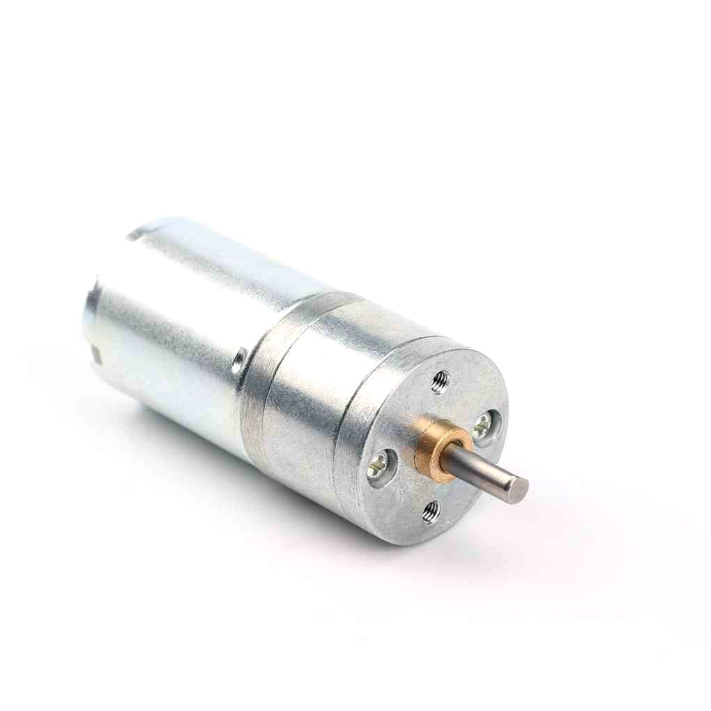
25GA-370 12V 12RPM DC Reducer Gear Motor
A compact 12V gear motor with built-in reduction gearbox — ideal for slow, high-torque applications like conveyors, camera sliders, and automated blinds.
Adding a Potentiometer for Manual Speed Control
A 10 kΩ potentiometer wired to Arduino’s A0 analog input allows manual speed adjustment without serial commands:
const int ENA = 3;
const int IN1 = 8;
const int IN2 = 9;
const int POT_PIN = A0;
const int DIR_BUTTON = 7;

bool motorForward = true;
int lastButtonState = HIGH;

void setup() {
  pinMode(ENA, OUTPUT);
  pinMode(IN1, OUTPUT);
  pinMode(IN2, OUTPUT);
  pinMode(DIR_BUTTON, INPUT_PULLUP);
}

void loop() {
  // Read potentiometer for speed
  int potValue = analogRead(POT_PIN);       // 0-1023
  int pwmValue = map(potValue, 0, 1023, 0, 255);

  // Read button for direction toggle
  int buttonState = digitalRead(DIR_BUTTON);
  if (buttonState == LOW && lastButtonState == HIGH) {
    motorForward = !motorForward;
    delay(50); // debounce
  }
  lastButtonState = buttonState;

  // Apply speed and direction
  analogWrite(ENA, pwmValue);
  if (motorForward) {
    digitalWrite(IN1, HIGH); digitalWrite(IN2, LOW);
  } else {
    digitalWrite(IN1, LOW);  digitalWrite(IN2, HIGH);
  }
  delay(10);
}
Wire the potentiometer: outer pins to 5 V and GND, centre wiper to A0. Wire the direction button between pin 7 and GND (INPUT_PULLUP handles the pull-up resistor in software).
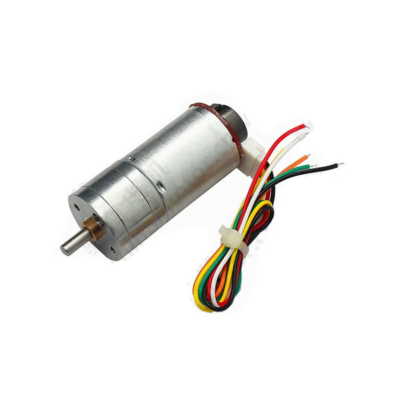
25GA-370 12V DC Gear Motor with Encoder
Same 12RPM gear motor but with a built-in quadrature encoder for closed-loop speed control — perfect for upgrading your circuit to PID-controlled motion.
Current Limiting and Motor Protection
DC motors can draw extremely high current during stall conditions (when the shaft is blocked). A 12 V motor rated at 500 mA running current may draw 5–10 A at stall. This stall current can destroy the motor driver, melt wiring, and cause fires.
Protection strategies:
- Fuse or resettable PTC fuse (polyfuse): Wire a fuse in the 12 V supply line rated at 1.5–2× the motor’s running current. It blows (or resets automatically for a polyfuse) during stall.
- Software current monitoring: Use a current sensing resistor (0.1 Ω, 1 W) in series with the motor and read the voltage drop via an Arduino analog input. If current exceeds a threshold, cut power immediately via the ENA pin.
- Thermal protection: L298N includes thermal shutdown at approximately 150°C junction temperature. Ensure heat sinking is adequate for your application.
- Flyback/freewheeling diodes: The L298N module includes these. If using discrete transistors, always add diodes across each switch to protect against inductive voltage spikes when the motor is switched off.
Freewheeling Diodes and Why They Matter
When you switch off a DC motor (or any inductive load), the magnetic field stored in the motor’s coils collapses and generates a reverse voltage spike. Without freewheeling diodes, this spike can reach hundreds of volts for just a few microseconds—enough to instantly destroy transistors, MOSFETs, and microcontrollers.
Freewheeling diodes (also called flyback diodes or snubber diodes) are placed in reverse bias across each switching element. When the inductive spike occurs, these diodes conduct, providing a safe recirculation path for the coil current and clamping the voltage to a safe level (one diode forward voltage drop above supply, approximately +0.7 V above VCC).
The L298N module already includes these diodes. If you build a discrete H-bridge with MOSFETs, always add fast-recovery diodes (like 1N4007 for low-frequency, or UF4007 for PWM switching applications) across each MOSFET drain-to-source.
Troubleshooting Common Issues
Motor doesn’t spin at all
- Check that the ENA jumper is removed and a PWM signal is connected (or leave the jumper for always-enabled at full speed)
- Verify common ground between Arduino and 12 V supply
- Measure voltage at L298N motor output pins with a multimeter while commanding motion
Motor spins in one direction only
- Verify IN1 and IN2 are toggling as expected using Serial.print() debugging
- Check that both IN pins are connected and not floating
Motor runs at full speed regardless of PWM value
- The ENA jumper is still installed — remove it and connect ENA to the Arduino PWM pin
Arduino resets when motor starts
- Insufficient power supply — motor startup current surge is causing voltage sag on the 5 V rail
- Add a 100 µF electrolytic capacitor across the Arduino’s 5 V and GND pins
- Use a separate power supply for the motor, not the Arduino’s onboard regulator

25GA-370 12V 1360RPM DC Gear Motor
High-speed variant of the 25GA-370 series at 1360 RPM — great for fan-speed control, conveyor prototypes, and projects where faster rotation is needed.
Recommended Products
Build your 12 V motor control circuit with these quality components from Zbotic:
25GA-370 12V 12RPM DC Reducer Gear Motor
Compact 12V gear motor with robust reduction gearbox — ideal for low-speed, high-torque bidirectional control applications.
25GA-370 12V DC Gear Motor with Encoder
Same reliable motor with quadrature encoder — add closed-loop PID speed control for precision applications.
Frequently Asked Questions
Can I control a 12V motor directly from Arduino pins?
No. Arduino digital output pins can source or sink a maximum of 40 mA. A 12 V DC motor typically draws 200 mA to 5 A depending on load. Connecting a motor directly to an Arduino pin will damage the pin and possibly the entire microcontroller. Always use a motor driver like L298N or a MOSFET circuit between the Arduino and motor.
What is the difference between L293D and L298N?
The L293D can drive up to 600 mA per channel, includes built-in flyback diodes, and can be powered from the same 5 V as the logic. The L298N handles up to 2 A per channel (4 A peak), supports up to 46 V motor supply, but requires external flyback diodes on the bare IC (most modules include them). For 12 V motors above 600 mA, use L298N or a MOSFET H-bridge.
Why does my motor slow down under load even with full PWM?
DC motor speed is proportional to back-EMF, which depends on actual shaft RPM. Under mechanical load, the motor slows, back-EMF drops, and more current flows (potentially limited by the driver). To maintain constant speed under varying load, implement closed-loop speed control using an encoder and a PID algorithm.
What PWM frequency should I use for DC motor control?
Arduino’s default 490 Hz (pins 3, 11) and 980 Hz (pins 5, 6) are generally fine for motor control. Higher frequencies (20–40 kHz) are preferred for silent operation (ultrasonic range, inaudible) and reduce switching losses in MOSFETs. For L298N with large motors, the default Arduino PWM frequency is adequate.
Can I control two motors independently with one L298N?
Yes. The L298N is a dual H-bridge module. Channel A (IN1, IN2, ENA, OUT1, OUT2) controls Motor 1, and Channel B (IN3, IN4, ENB, OUT3, OUT4) controls Motor 2, completely independently. This is ideal for differential drive robots.
Conclusion
Controlling 12 V DC motor speed and direction from Arduino is a core skill that unlocks hundreds of project possibilities. The L298N module makes hardware implementation straightforward, and the Arduino analogWrite() function handles PWM generation with a single line of code. The key principles to remember are: always share a common ground, never connect a motor directly to Arduino pins, use flyback diodes, and implement soft-start acceleration to avoid large current spikes.
Once you master single-motor control, you can scale up to dual-motor differential drive robots, multi-axis CNC machines, and closed-loop PID-controlled systems with encoders. The foundation you build here applies to every DC motor project you’ll ever build.
Shop Zbotic’s full range of DC motors and drivers to get started on your next build.


Add comment