
Using a transistor as a switch in NPN and PNP circuits is one of the most fundamental skills in electronics. Whether you are controlling a motor, driving an LED strip, switching a relay, or interfacing a 5V Arduino with a 12V load, a transistor switch is the most reliable and efficient solution. This guide explains the theory and practical wiring of both NPN and PNP transistor switch circuits with clear Arduino examples using commonly available components like the BC547 and 2N2222.
Table of Contents
- Why Use a Transistor as a Switch?
- Transistor Basics: NPN vs PNP
- NPN Transistor Switch Circuit
- PNP Transistor Switch Circuit
- Base Resistor Calculation: The Critical Step
- Arduino Examples: NPN and PNP Switching
- Practical Tips: Protection, MOSFETs, and Common Mistakes
- Frequently Asked Questions
Why Use a Transistor as a Switch?
A microcontroller like the Arduino Uno can only source or sink about 20–40 mA per GPIO pin. Most real-world loads — DC motors, relays, solenoids, LED strips, buzzers — require far more current than that. Connecting them directly to a GPIO pin risks burning out the microcontroller permanently.
A transistor solves this problem by acting as an electronically controlled switch. A small base current (milliamps from the Arduino) controls a much larger collector current (amps from an external power supply) flowing through the load. This is called current amplification, and the ratio is called hFE or beta (β).
Advantages of transistor switches over mechanical switches:
- No moving parts — silent, fast, and reliable
- Switching speeds up to hundreds of kilohertz (for PWM control)
- Logic-level compatible (3.3V or 5V GPIO can drive them directly with a base resistor)
- Available in tiny packages (TO-92, SOT-23) that fit on breadboards
- Cost-effective: BC547 costs just a few rupees per piece
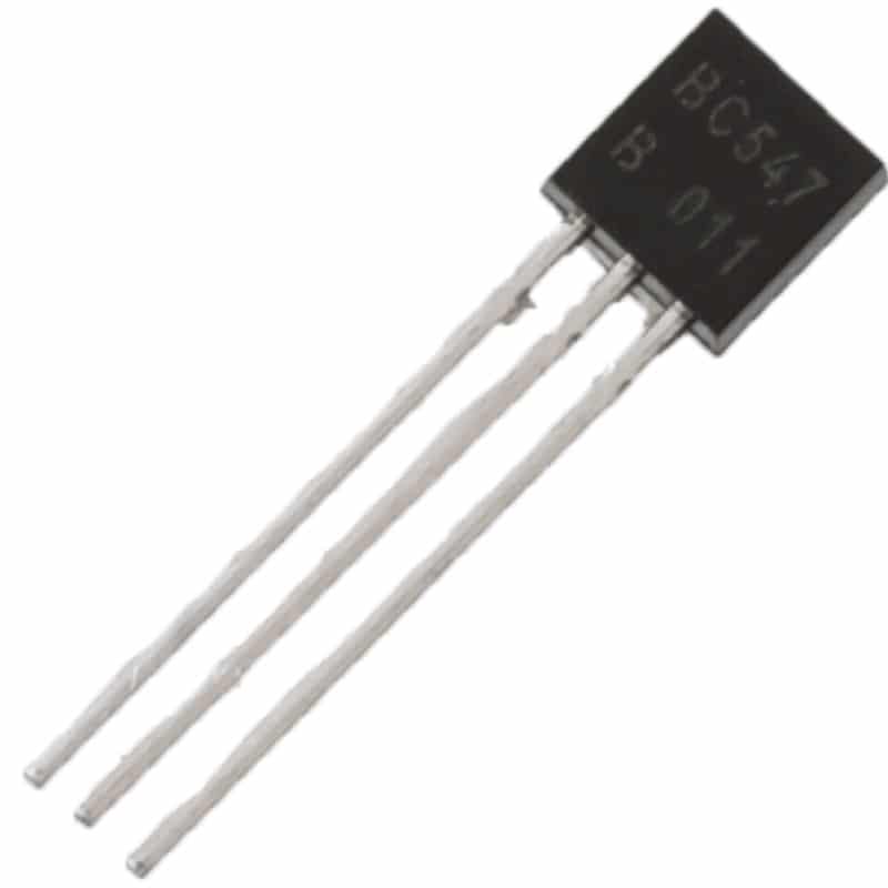
BC547 NPN 100mA Transistor TO-92 (Pack of 10)
The most popular general-purpose NPN transistor in India. hFE 110–800, perfect for logic-level switching, LED drivers, and relay control circuits.
Transistor Basics: NPN vs PNP
A Bipolar Junction Transistor (BJT) has three terminals: Base (B), Collector (C), and Emitter (E). The two types — NPN and PNP — differ in how they are biased to switch on.
NPN Transistor
- Structure: N-P-N semiconductor layers
- Symbol: Arrow on emitter points OUT (away from base)
- Switches ON when Base is HIGH (positive voltage relative to emitter)
- Current flows from Collector to Emitter when ON
- Load is connected between the positive supply and the Collector
- Common examples: BC547, BC548, 2N2222, 2N3904
PNP Transistor
- Structure: P-N-P semiconductor layers
- Symbol: Arrow on emitter points IN (toward base)
- Switches ON when Base is LOW (negative voltage relative to emitter)
- Current flows from Emitter to Collector when ON
- Load is connected between the negative supply (GND) and the Collector
- Common examples: BC557, BC558, 2N2907, 2N3906
The memory trick: NPN = Not Pointing iN (emitter arrow points out). PNP = Pointing iN Proudly (emitter arrow points in).
For most Arduino switching applications, the NPN configuration is simpler and more intuitive — your load connects to the positive rail, and the transistor pulls the other end to ground when activated.
NPN Transistor Switch Circuit
The NPN transistor switch is the most common configuration for Arduino projects. Here is how it works:
Circuit Connection (NPN Low-Side Switch)
+VCC (e.g. 12V)
   |
 [LOAD] (e.g. relay coil, motor, LED strip)
   |
   C  (Collector)
   |
   B ----- [Rbase] ----- Arduino GPIO (HIGH = 5V)
   |
   E  (Emitter)
   |
  GND (common with Arduino GND)
When Arduino GPIO is HIGH (5V): Base-Emitter junction is forward-biased → transistor saturates → Collector-Emitter acts like a closed switch → current flows through the load → load is ON.
When Arduino GPIO is LOW (0V): No base current → transistor is cut off → Collector-Emitter acts like an open switch → no current through load → load is OFF.
Important: Inductive Load Protection Diode
When switching inductive loads (relays, motors, solenoids), always add a freewheeling diode (1N4007 or 1N4148) in parallel with the load, cathode toward +VCC. When the transistor turns OFF, the collapsing magnetic field generates a voltage spike (back-EMF) that can exceed 100V and destroy the transistor without this diode.
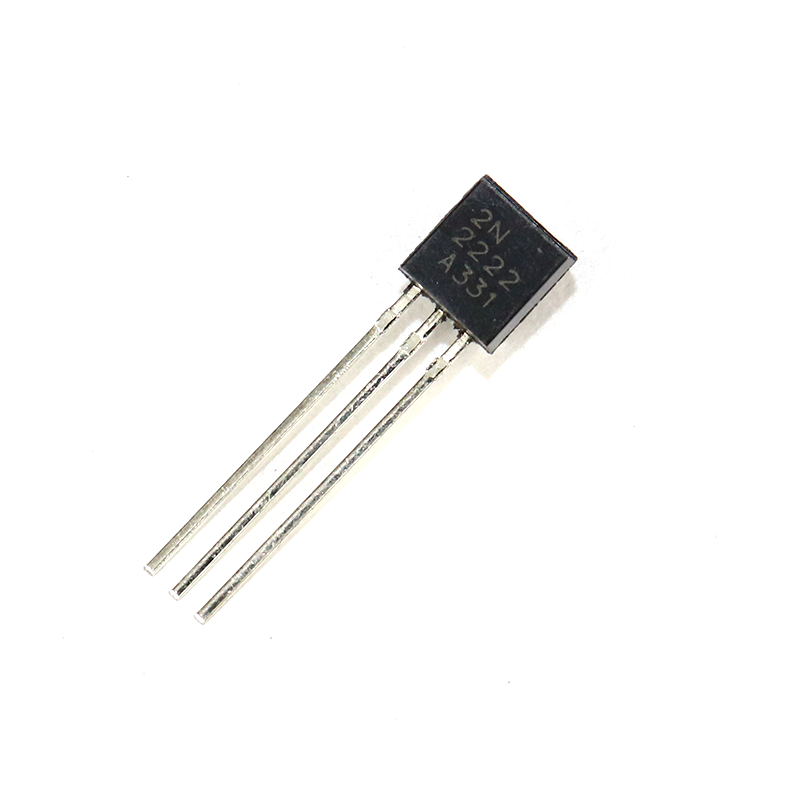
2N2222 NPN Transistor (Pack of 20)
Higher-current NPN transistor (600mA, 40V), ideal for driving relays and heavier loads. Popular in motor switching and power electronics projects.
PNP Transistor Switch Circuit
The PNP transistor is used as a high-side switch — the load connects between the transistor’s collector and ground, while the emitter connects to the positive supply. The transistor turns ON when the base is pulled LOW.
Circuit Connection (PNP High-Side Switch)
+VCC (e.g. 5V or 12V)
   |
   E  (Emitter)
   |
   B ----- [Rbase] ----- Arduino GPIO (LOW = 0V turns ON)
   |
   C  (Collector)
   |
 [LOAD]
   |
  GND
When Arduino GPIO is LOW (0V): Base is pulled low relative to emitter (+VCC) → transistor turns ON → current flows Emitter→Collector→Load → load is ON.
When Arduino GPIO is HIGH (5V): Base voltage equals emitter voltage → no base current → transistor OFF → load is OFF.
Note: With a PNP switch, HIGH on the GPIO means OFF, and LOW means ON. This logic inversion is important to account for in your code.
When to Use PNP Instead of NPN?
- When the load’s negative terminal needs to connect to a specific ground other than the common ground
- In complementary push-pull output stages (class B amplifier, H-bridge drivers)
- When interfacing with active-low control signals (e.g. some relay modules)
Base Resistor Calculation: The Critical Step
The base resistor limits the current flowing into the transistor’s base. Too much base current damages the transistor; too little and the transistor won’t saturate (fully switch on), causing it to heat up and waste power.
The Formula
For saturation (fully ON state), you need the base current (Ib) to be at least Ic/hFE, where Ic is the collector current and hFE is the transistor’s current gain. A safety factor of 5–10× is applied to guarantee saturation across all transistor samples and temperatures:
Rbase = (Vin − Vbe) / Ib_required

Where:
  Vin  = GPIO output voltage (5V for Arduino Uno)
  Vbe  = Base-Emitter forward voltage (~0.7V for silicon BJT)
  Ib_required = (Ic / hFE_min) × saturation_factor (typically ×10)
Worked Example: BC547 Switching a 100mA Relay Coil
- Relay coil current (Ic) = 100 mA = 0.1 A
- BC547 hFE minimum = 110
- Required Ib (with ×10 saturation factor) = (0.1 / 110) × 10 = 9.09 mA
- Rbase = (5V − 0.7V) / 0.00909 = 4.3V / 0.00909 = 473 Ω
- Choose nearest standard resistor: 470 Ω
For a simple LED (20 mA), the base resistor would be around 10 kΩ — much larger, because the load current is small. A common rule of thumb for LED switching with BC547 and 5V Arduino: use 10kΩ base resistor.
Arduino Examples: NPN and PNP Switching
Example 1: NPN Switch for LED with BC547
Hardware: BC547 (NPN), 10kΩ base resistor, LED with 330Ω series resistor, breadboard, 5V Arduino Uno.
Connect: Arduino pin 9 → 10kΩ → BC547 Base. BC547 Collector → 330Ω → LED → +5V. BC547 Emitter → GND.
// NPN LED switch with BC547
const int transistorPin = 9;

void setup() {
  pinMode(transistorPin, OUTPUT);
}

void loop() {
  digitalWrite(transistorPin, HIGH); // LED ON
  delay(1000);
  digitalWrite(transistorPin, LOW);  // LED OFF
  delay(1000);
}
Example 2: NPN Relay Switch with 2N2222
Hardware: 2N2222 (NPN), 1kΩ base resistor, 1N4007 flyback diode, 5V relay, 12V external power supply for relay, Arduino.
Connect: Arduino pin 8 → 1kΩ → 2N2222 Base. 2N2222 Collector → relay coil → +12V. 1N4007 across relay coil (cathode to +12V). 2N2222 Emitter → GND (common with Arduino GND).
// NPN relay switch with 2N2222
const int relayPin = 8;

void setup() {
  pinMode(relayPin, OUTPUT);
  digitalWrite(relayPin, LOW); // Relay OFF on start
}

void loop() {
  digitalWrite(relayPin, HIGH); // Relay ON
  delay(2000);
  digitalWrite(relayPin, LOW);  // Relay OFF
  delay(2000);
}
Example 3: PWM Speed Control with NPN Transistor
You can use PWM (analogWrite) to control the average current through the load — useful for LED brightness control or DC motor speed control.
// PWM brightness control via NPN
const int transistorPin = 9; // PWM-capable pin

void setup() {
  pinMode(transistorPin, OUTPUT);
}

void loop() {
  for (int brightness = 0; brightness = 0; brightness--) {
    analogWrite(transistorPin, brightness);
    delay(10);
  }
}
Practical Tips: Protection, MOSFETs, and Common Mistakes
Common Mistakes to Avoid
- Forgetting the base resistor: Connecting the GPIO pin directly to the base will draw too much current and may damage the Arduino output pin.
- Reversed transistor orientation: BC547 and 2N2222 have different pin-out orders! Always check the datasheet for your exact package (TO-92). Hold the flat face toward you: EBC for BC547, CBE for 2N2222.
- No common ground: If your load is powered by a separate 12V supply, ensure the 12V GND is connected to the Arduino GND. Without this, the transistor base voltage has no reference.
- Missing flyback diode on inductive loads: Causes mysterious transistor failures after a few switching cycles.
- Driving too much current with BC547: BC547 is rated 100mA max. For loads above 100mA, switch to 2N2222 (600mA) or use a MOSFET like IRFZ44N for amp-level loads.
NPN BJT vs MOSFET: Which Should You Use?
For logic-level switching in Arduino projects, BJT transistors (BC547, 2N2222) are excellent for loads up to 500mA. For higher-power switching (motors, LED strips, heating elements), logic-level MOSFETs like IRLZ44N or IRLB8721 are preferable because:
- MOSFETs are voltage-controlled (almost zero gate current required)
- MOSFETs have very low on-resistance (RDS_on), meaning less heat even at high currents
- Logic-level MOSFETs switch fully ON at 3.3V–5V gate voltage
For simple, low-power switching (LEDs, small buzzers, relay coils), the BJT is simpler to understand and costs less.
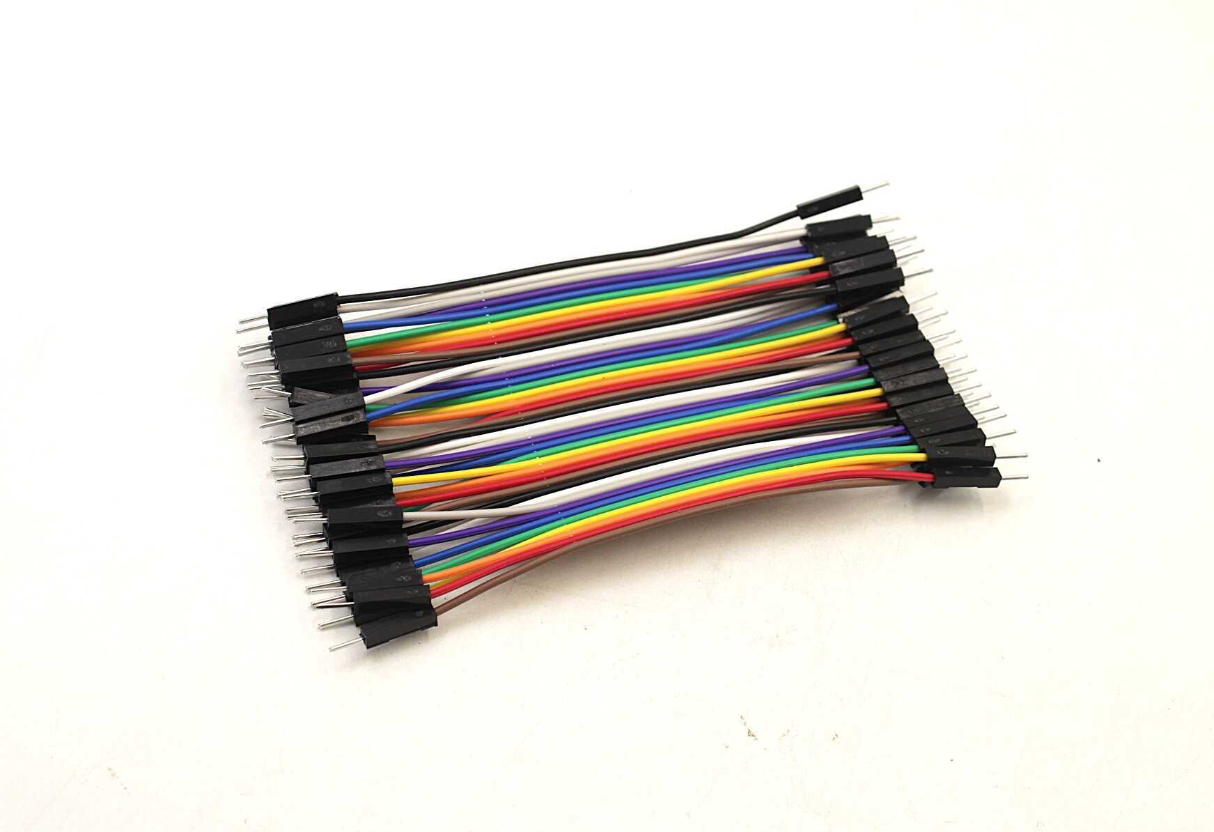
10CM Male To Male Breadboard Jumper Wires — 40Pcs
Standard 2.54mm pitch male-to-male jumper wires, essential for breadboarding transistor switch circuits. 40 wires in a pack for full circuit flexibility.
Darlington Transistors: When You Need More Gain
A Darlington pair connects two BJTs in series, multiplying their hFE values together. For example, two BC547 transistors each with hFE=200 combined give hFE=40,000. The ULN2003 and ULN2803 ICs are popular Darlington arrays for driving multiple relay coils from a single IC. The trade-off is a higher Vce(sat) of about 1–1.2V instead of 0.2V for a single BJT.

LCR-T4 Transistor Tester & Component Identifier
Automatically identifies NPN/PNP transistors, diodes, MOSFETs and displays hFE and pin layout — essential for verifying unknown transistors from your component bin.
Protect Your Arduino: 12V Power Supplies
When switching 12V loads (relays, motors), use a dedicated 12V power supply rather than powering the load from the Arduino’s VIN pin. The 12V supply and the Arduino can share a common ground, but the load current should never pass through the Arduino’s regulator.
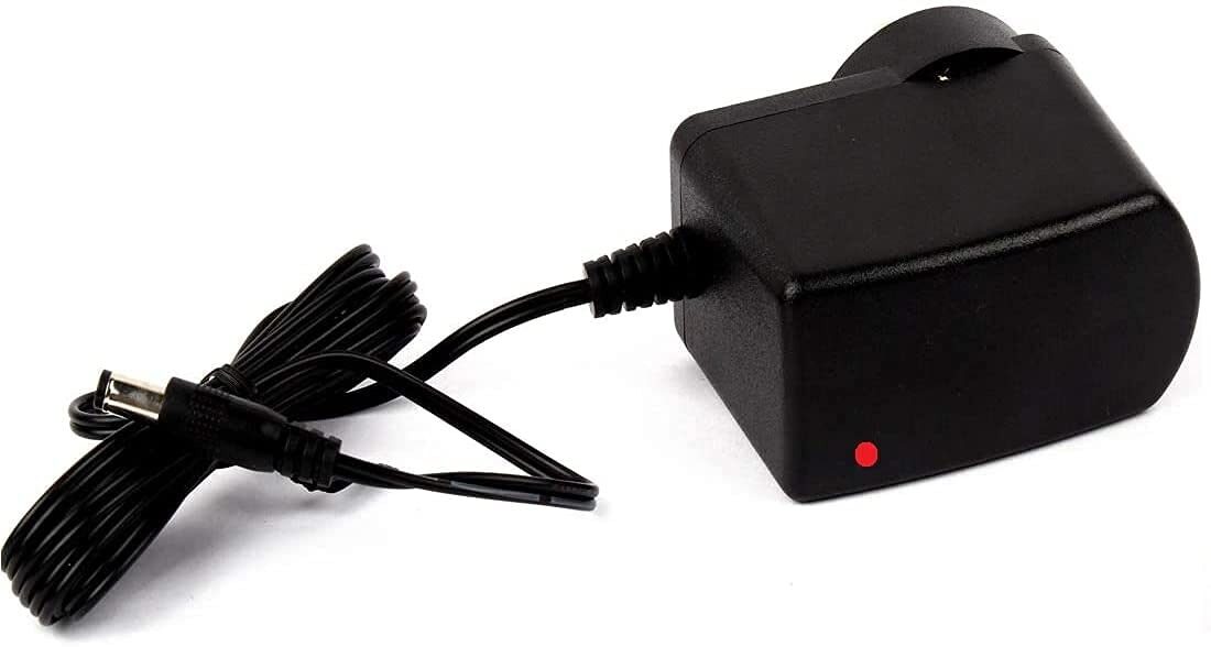
12V 2A Power Supply with 5.5mm DC Plug Adapter
Reliable 12V 2A regulated adapter for powering relay loads, LED strips, and motor driver circuits alongside your Arduino project.
Frequently Asked Questions
What is the difference between NPN and PNP transistor in simple terms?
NPN turns ON when you apply a positive voltage to the base — like pressing a button with HIGH. PNP turns ON when you pull the base LOW — like pressing a button by grounding it. For most Arduino projects, NPN is the easier choice because it matches the HIGH = ON logic of microcontrollers.
Can I use BC547 to switch a 12V relay?
Yes, provided the relay coil draws less than 100mA (most 5V/12V relays draw 60–90mA). Use a 1kΩ base resistor, add a 1N4007 flyback diode across the relay coil, and ensure the 12V supply GND is connected to Arduino GND. Use the 2N2222 if you need slightly more headroom.
My transistor is getting hot — what is wrong?
A transistor gets hot when it is not fully saturated. Check: (1) Is your base resistor value correct? Reduce it to increase base current. (2) Is the load current within the transistor’s rating? (3) Are you using PWM at very low duty cycles — the transistor may be spending a lot of time in the active region rather than cutoff or saturation. Switch to a MOSFET for high-frequency PWM applications.
What resistor value should I use for BC547 with a 5V Arduino?
For small loads (LEDs, small buzzers under 20mA): 10kΩ. For relay coils (60–100mA): 1kΩ. For intermediate loads: calculate using the formula Rbase = (5V − 0.7V) / (Ic / hFE_min × 10). When in doubt, 1kΩ works safely for most relay-switching applications with BC547.
What is the pinout of BC547 vs 2N2222?
With the flat face of the TO-92 package facing you and legs pointing down — BC547 pin order is E-C-B (left to right), while 2N2222 (TO-92 metal can version) is E-B-C. The most common through-hole 2N2222A plastic TO-92 is E-B-C. Always check the datasheet for the exact part you have. An LCR component tester will auto-identify the pinout for unknown transistors.
Conclusion: Transistor Switches Unlock the Full Power of Your Arduino
Mastering the NPN transistor switch is the gateway to controlling real-world loads with any microcontroller. Once you understand the base resistor calculation and the importance of flyback diodes for inductive loads, you can design reliable switching circuits for relays, motors, LED strips, and much more. Stock up on BC547 and 2N2222 transistors, keep a pack of 1kΩ and 10kΩ resistors handy, and use the LCR tester to verify any unknown transistors from your component bin. Happy making!


Add comment