
Table of Contents
- What Is a Solenoid Valve?
- Types of Solenoid Valves
- Why You Cannot Drive a Solenoid Directly from Arduino
- Method 1: Relay Module Control
- Method 2: MOSFET Control (PWM Compatible)
- The Critical Flyback Diode
- 12V Solenoid Valve Circuit
- 24V Solenoid Valve Circuit
- Arduino Code Examples
- Project Ideas
- Recommended Products
- FAQ
What Is a Solenoid Valve?
A solenoid valve is an electromechanically operated valve used to control the flow of liquids or gases. It consists of a coil of wire (the solenoid) wound around a movable ferromagnetic plunger. When current flows through the coil, it creates a magnetic field that pulls the plunger and opens (or closes) the valve orifice. When current is removed, a spring returns the plunger to its resting position.
Solenoid valves are used everywhere in automation:
- Water irrigation and drip systems
- Pneumatic cylinder control
- Aquarium CO2 injection
- Automated coffee machines
- Fuel injection in engines
- Hydraulic control systems
- 3D printer filament cutters
- Gas pipeline safety shutoffs
Types of Solenoid Valves
By Operation Mode
- Normally Closed (NC): Valve is closed when de-energised, opens when power is applied. Most common type. Safe for fail-safe applications — the valve closes if power is lost.
- Normally Open (NO): Valve is open when de-energised, closes when power is applied. Used where you want flow to continue even if power fails.
- Bistable (Latching): Uses a pulse to open and another pulse to close. Holds position without continuous power — useful for battery-powered applications.
By Port Configuration
- 2/2 valve: 2 ports (in and out), 2 positions (open/closed). Most basic and common for simple on/off control.
- 3/2 valve: 3 ports, 2 positions. Used to control single-acting pneumatic cylinders (extends on power, retracts via spring).
- 5/2 valve: 5 ports, 2 positions. Controls double-acting pneumatic cylinders (extends and retracts under power).
By Voltage
The most common solenoid valve voltages for maker and automation projects in India:
- 12V DC — most popular for maker projects; compatible with 12V batteries, car batteries, and switching power supplies
- 24V DC — industrial standard; most PLC-based systems use 24V; higher voltage allows thinner wiring over long distances
- 220V AC — mains-powered industrial valves; require solid-state relays for microcontroller control
Why You Cannot Drive a Solenoid Directly from Arduino
A typical 12V solenoid valve coil draws 200 mA to 1 A of current. An Arduino digital output pin can source only 40 mA maximum (and total GPIO current is limited to 200 mA). Connecting a solenoid directly to an Arduino pin will:
- Immediately damage the GPIO pin
- Potentially damage the ATmega microcontroller permanently
- Cause erratic behaviour even if not immediate damage
Additionally, solenoids are inductive loads. When you switch off the current, the collapsing magnetic field generates a high-voltage spike (back-EMF) that can be 10–100 times the supply voltage. Without protection, this spike will destroy any transistor, MOSFET, or relay connected to the solenoid.
You need an intermediary switching circuit — either a relay module or a MOSFET — plus a flyback diode to suppress the back-EMF spike.
Method 1: Relay Module Control
A relay module uses a small electromechanical relay to switch the high-current solenoid circuit from a low-current Arduino output. It provides complete galvanic isolation between the control circuit and the load circuit.
Advantages of Relay Method
- Works with any voltage solenoid (12V, 24V, 220V AC) — the relay switches any voltage
- Complete isolation — no risk of high voltage reaching the Arduino
- Simple to wire — no transistors or diodes needed (most relay modules include them)
- Easy to understand for beginners
Disadvantages of Relay Method
- Relay contacts wear out after ~100,000 operations (not suitable for high-frequency switching)
- Relay has ~10 ms switching delay — too slow for PWM or high-speed control
- Relay produces an audible click — unsuitable for quiet environments
- Mechanical vibration can be an issue in sensitive sensor setups
Relay Wiring
- Connect relay module IN pin to an Arduino digital pin (e.g., D7)
- Connect relay module VCC to Arduino 5V (or external 5V if using a large relay)
- Connect relay module GND to Arduino GND
- Wire the solenoid valve’s positive lead to the relay’s COM (common) terminal
- Wire the relay’s NO (normally open) terminal to the positive terminal of your 12V or 24V supply
- Wire the solenoid’s negative lead to the supply’s negative terminal
Note: Most relay modules are active LOW — writing LOW to the IN pin activates the relay, HIGH deactivates it. Check your specific module’s documentation.
Method 2: MOSFET Control (PWM Compatible)
For applications requiring fast switching, PWM speed control (e.g., proportional valves), or silent operation, use an N-channel logic-level MOSFET such as the IRLZ44N or IRL2203N.
Advantages of MOSFET Method
- Supports PWM — allows proportional/partial valve opening on specially designed proportional solenoids
- Switching frequency up to hundreds of kHz
- Silent operation
- No mechanical wear
- Very low power loss when fully on (RDS_on typically <0.02 Ω)
MOSFET Circuit for 12V Solenoid
Components needed:
- N-channel MOSFET: IRLZ44N (logic-level, 5V gate compatible)
- Gate resistor: 100–220 Ω (limits gate current and reduces ringing)
- Gate pull-down resistor: 10 kΩ (ensures MOSFET is off when Arduino pin is floating)
- Flyback diode: 1N4007 or 1N5819 (Schottky preferred)
Wiring:
- Connect MOSFET Source to circuit GND
- Connect MOSFET Drain to the negative leg of the solenoid
- Connect solenoid positive leg to 12V supply positive
- Place flyback diode across the solenoid: cathode (stripe) to 12V positive, anode to solenoid negative (MOSFET drain side)
- Connect a 100Ω resistor in series between Arduino pin and MOSFET Gate
- Connect a 10kΩ resistor from MOSFET Gate to GND (pull-down)
- Connect MOSFET Source GND and Arduino GND together
The Critical Flyback Diode
This deserves special emphasis: always fit a flyback diode across any inductive load (solenoids, relay coils, DC motors). Without it, the back-EMF spike when the solenoid is switched off can easily reach 100–200V on a 12V system, instantly destroying your MOSFET, transistor, or Arduino GPIO.
- 1N4007 — standard rectifier diode, handles 1A/1000V. Adequate for most solenoids but has slower recovery.
- 1N5819 — Schottky diode, much faster recovery, lower forward voltage. Better for high-frequency switching (PWM) applications.
- Orientation: cathode (band side) to the positive supply rail; anode to the MOSFET drain/switched side.
12V Solenoid Valve Circuit
A complete 12V solenoid circuit using a relay module and Arduino Uno:
- Power supply: 12V DC (1A or higher, rated for solenoid current)
- Relay module: single-channel 5V relay module (with opto-isolation)
- Arduino: any model with a 5V digital output
- Solenoid valve: 12V NC (normally closed) 2/2 valve
The key advantage of using a relay module over a bare relay: the module includes the flyback diode across its coil and an optocoupler for isolation. You only need to provide the solenoid-side diode for additional protection.
24V Solenoid Valve Circuit
24V solenoids are common in industrial and agricultural applications (e.g., irrigation zone controllers). The control circuit is identical to 12V — only the power supply voltage changes. Use the MOSFET method with an IRLZ44N (rated 55V) for 24V solenoids. A relay module will also work as long as the relay contacts are rated for 24V (virtually all standard relay modules support up to 250V AC / 30V DC on the contacts).
For 24V systems drawing more than 1A per valve, use a higher-current MOSFET such as the IRF3205 (rated 55V, 110A). Ensure your flyback diode is rated above 24V (1N4007 at 1000V reverse voltage is fine).
Arduino Code Examples
Basic On/Off Control (Relay Module, Active LOW)
#define RELAY_PIN 7

void setup() {
  pinMode(RELAY_PIN, OUTPUT);
  digitalWrite(RELAY_PIN, HIGH); // Ensure relay is off at startup
}

void loop() {
  // Open solenoid valve for 5 seconds
  digitalWrite(RELAY_PIN, LOW);  // Active LOW: LOW = relay ON = valve opens
  delay(5000);

  // Close solenoid valve for 10 seconds
  digitalWrite(RELAY_PIN, HIGH); // HIGH = relay OFF = valve closes (NC type)
  delay(10000);
}
Timed Irrigation Controller (Multiple Zones)
#define ZONE1_PIN 4
#define ZONE2_PIN 5
#define ZONE3_PIN 6
#define ZONE_ON_TIME 30000  // 30 seconds per zone

int zones[] = {ZONE1_PIN, ZONE2_PIN, ZONE3_PIN};

void setup() {
  for (int i = 0; i < 3; i++) {
    pinMode(zones[i], OUTPUT);
    digitalWrite(zones[i], HIGH); // All valves closed
  }
  Serial.begin(9600);
}

void openZone(int zonePin) {
  Serial.print("Opening zone on pin ");
  Serial.println(zonePin);
  digitalWrite(zonePin, LOW);  // Open valve
  delay(ZONE_ON_TIME);
  digitalWrite(zonePin, HIGH); // Close valve
  delay(1000);  // Brief pause between zones
}

void loop() {
  for (int i = 0; i < 3; i++) {
    openZone(zones[i]);
  }
  delay(3600000); // Wait 1 hour before next irrigation cycle
}
MOSFET PWM Control (Proportional Valve)
#define MOSFET_PIN 9  // Must be PWM-capable pin

void setup() {
  pinMode(MOSFET_PIN, OUTPUT);
}

void loop() {
  // Ramp from 0% to 100% duty cycle
  for (int duty = 0; duty <= 255; duty++) {
    analogWrite(MOSFET_PIN, duty);
    delay(20);
  }
  delay(1000);

  // Ramp back down
  for (int duty = 255; duty >= 0; duty--) {
    analogWrite(MOSFET_PIN, duty);
    delay(20);
  }
  delay(1000);
}
Project Ideas
- Smart Garden Irrigation: Combine soil moisture sensors (capacitive sensor modules) with 12V solenoid valves on relay modules. Arduino opens each zone only when moisture drops below threshold.
- Aquarium CO2 Controller: Connect a CO2 solenoid valve to a relay controlled by a pH probe and Arduino. Opens valve when pH rises above target, closes when target pH is reached.
- Pneumatic Robot Gripper: Use a 12V 3/2 NC solenoid valve to control a pneumatic cylinder for a robot end effector. Arduino activates valve to grip, releases to open.
- Water Rocket Launcher: Remotely trigger a 12V solenoid valve from an Arduino + wireless module (433 MHz or LoRa) to release pressurised water at a precise moment.
- Toilet Tank Auto-Refill: Float switch + solenoid valve controlled by Arduino to refill a toilet tank or water storage — eliminates noise from constantly running fill valve.
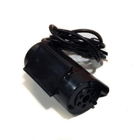
12V High Quality DC Mini Submersible Pump
Compact 12V submersible pump for water-flow projects. Pair with a 12V solenoid valve and relay module to build a complete automated irrigation or liquid dispensing system.
Recommended Products
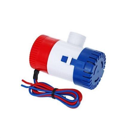
24VDC 350 GPH Bilge Submersible Pump
High-flow 24V submersible pump for industrial and marine applications. Control with a 24V relay or MOSFET circuit and Arduino for automated liquid management systems.
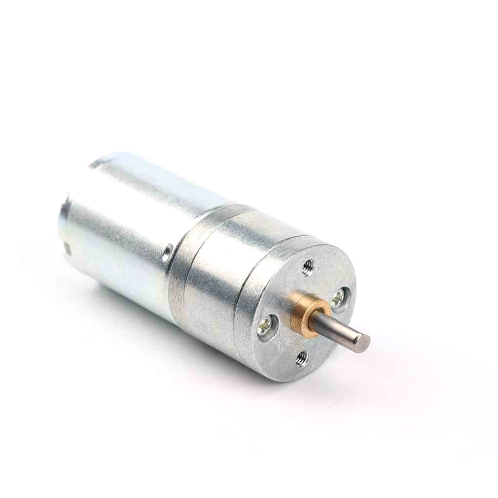
25GA-370 12V 12RPM DC Reducer Gear Motor
Combine with a solenoid valve in hybrid automation builds — use the gear motor for slow movement, solenoid for fast on/off fluid control. Both controllable from the same Arduino relay outputs.
Frequently Asked Questions
Can a 12V solenoid valve be controlled by a 5V relay module?
Yes. The relay module coil runs on 5V (powered by your Arduino’s 5V pin), while the relay’s switch contacts can handle up to 30V DC / 250V AC. The 12V solenoid is connected to the relay’s switch contacts — it is completely separate from the 5V control side. This is the beauty of a relay: it provides galvanic isolation between the two voltage domains.
My solenoid valve gets very hot during extended operation. Is this normal?
Mild warmth is normal — solenoid coils are resistive and dissipate power as heat. However, if the valve is too hot to touch after 10 minutes, either the coil resistance is too low for the applied voltage (check voltage rating), or the valve is being held open for long periods. Some solenoids are rated for intermittent duty only (short pulses) rather than continuous operation. Check the manufacturer’s duty cycle rating.
Do I need a separate power supply for the solenoid?
Yes, for 12V and 24V solenoids. Your Arduino cannot supply 12V or 24V. Use a dedicated DC power supply (or a suitable battery) rated above the solenoid’s operating current. Connect the power supply ground and Arduino ground together for a common reference.
What is the difference between a normally closed and normally open solenoid valve?
In a normally closed (NC) valve, the default state (no power) is closed — fluid cannot flow. Applying power opens the valve. NC is used for safety-critical applications: if power fails, the valve closes and flow stops. In a normally open (NO) valve, the default state is open — fluid flows without power. Applying power closes the valve. NO is used where continuous flow is needed and you only want to interrupt it temporarily.
Can I use a transistor instead of a relay or MOSFET?
Yes, an NPN transistor (like 2N2222, BC547, or TIP120) can switch a solenoid. However, BJT transistors have a higher saturation voltage than MOSFETs (0.2–0.5 V vs 0.05 V), meaning they dissipate more power and get hotter. For currents above 0.5 A, use a Darlington transistor (TIP120) or a logic-level MOSFET. Always include the flyback diode regardless of transistor type.
Conclusion
Controlling solenoid valves with Arduino is straightforward once you understand the two fundamental requirements: a driver circuit (relay module or MOSFET) to handle the valve’s current demand, and a flyback diode to protect the circuit from back-EMF spikes. For beginners, start with a 5V relay module — it is the simplest and safest method. For advanced builds requiring PWM, high-frequency switching, or silent operation, use a logic-level MOSFET with a Schottky flyback diode.
With these techniques, you can build irrigation controllers, pneumatic systems, liquid dispensers, and many other automation projects. Explore Zbotic’s full range of actuators and pumps for your next automation project.


Add comment