
Surface-mount device (SMD) components dominate modern electronics manufacturing — from smartphones to industrial controllers. Yet for many hobbyists and students, the world of tiny SMD packages remains mysterious and intimidating. This complete SMD components guide demystifies every common package size, explains how 0402, 0603, and 0805 sizes differ, and gives you practical tips for working with SMD parts in your projects.
What Are SMD Components?
SMD stands for Surface-Mount Device. Unlike through-hole components (which have wire leads that pass through holes in a PCB), SMD components sit directly on the surface of the board and are soldered to pads. This enables much smaller circuit boards, automated assembly, and components on both sides of the PCB.
SMD technology became mainstream in the 1980s and today accounts for over 90% of all components used in electronic manufacturing. Understanding SMD packages is essential for:
- Reading and ordering components for PCB designs
- Repairing modern circuit boards (phones, laptops, appliances)
- Designing compact custom PCBs in KiCad or EasyEDA
- Understanding component datasheets
SMD components include resistors, capacitors, inductors, diodes, transistors, integrated circuits, and more — all in standardized package sizes.
SMD Package Naming Convention Explained
The numeric codes used for SMD passive components (resistors, capacitors) follow a straightforward system — though there are two conflicting standards: Imperial (inch-based) and Metric (mm-based).
Imperial Codes (Most Common in India)
Imperial codes express the component’s dimensions in hundredths of an inch:
- 0402 = 0.04″ × 0.02″ = 1.0mm × 0.5mm
- 0603 = 0.06″ × 0.03″ = 1.6mm × 0.8mm
- 0805 = 0.08″ × 0.05″ = 2.0mm × 1.25mm
- 1206 = 0.12″ × 0.06″ = 3.2mm × 1.6mm
Metric Codes
Metric codes express dimensions in tenths of a millimeter. The same components in metric are:
- Imperial 0402 = Metric 1005 (1.0mm × 0.5mm)
- Imperial 0603 = Metric 1608 (1.6mm × 0.8mm)
- Imperial 0805 = Metric 2012 (2.0mm × 1.25mm)
When ordering from Indian distributors or global sites like LCSC, the imperial code is most commonly used. Always verify by checking the actual dimensions in millimeters.
Size Comparison: 0201 to 2512
| Package (Imperial) | Length × Width (mm) | Max Power (Resistor) | Solderable by Hand? |
|---|---|---|---|
| 0201 | 0.6 × 0.3 | 1/20W (50mW) | No (microscope needed) |
| 0402 | 1.0 × 0.5 | 1/16W (63mW) | Difficult (tweezers + magnifier) |
| 0603 | 1.6 × 0.8 | 1/10W (100mW) | Yes (with practice) |
| 0805 | 2.0 × 1.25 | 1/8W (125mW) | Yes (comfortable) |
| 1206 | 3.2 × 1.6 | 1/4W (250mW) | Easy |
| 1210 | 3.2 × 2.5 | 1/2W (500mW) | Easy |
| 2010 | 5.0 × 2.5 | 3/4W (750mW) | Easy |
| 2512 | 6.35 × 3.2 | 1W | Very easy |
0402 Package: Tiny but Capable
The 0402 package (1.0 × 0.5mm) is the smallest size that most electronics engineers work with regularly. At this scale, each component is approximately the size of a grain of sand. Handling 0402 components requires:
- Fine-tip precision tweezers (ESD safe)
- A magnifying glass or stereo microscope
- Fine-tip soldering iron (0.5-1mm tip)
- Fine solder (0.3-0.5mm diameter)
- Solder paste + hot air rework station (recommended)
0402 resistors are rated at 1/16W (63mW) maximum power. They’re used extensively in smartphones, wearables, and high-density PCBs where board space is at an absolute premium. For hobbyist projects, 0402 is rarely necessary unless you’re designing a compact wearable.
Tip: 0402 components are notorious for “tombstoning” during reflow — where one end lifts off the pad due to uneven solder melting. Careful solder paste application and balanced pad geometry prevents this.
0603 Package: The Hobbyist Sweet Spot
The 0603 package (1.6 × 0.8mm) represents the ideal balance between size and solderability for most hobbyist and small-scale production use. It’s significantly easier to handle than 0402 while still being very compact.
Key characteristics of 0603:
- Power rating: 1/10W (100mW) for resistors
- Voltage rating: up to 25V for capacitors (varies by dielectric)
- Available in virtually every common resistor and capacitor value
- Suitable for manual soldering with a fine iron tip
- Wide availability from Indian distributors and online stores
0603 is the recommended starting size if you’re new to SMD soldering. Many SMD practise kits use 0603 components specifically because they’re manageable with basic soldering skills and standard tools.
0805 Package: Easy to Hand Solder
The 0805 package (2.0 × 1.25mm) is the largest size that can still be considered “small.” At this size, hand soldering becomes genuinely comfortable, even for beginners. The pads are large enough to see clearly with the naked eye and solder without excessive difficulty.
0805 is an excellent choice for:
- Prototype PCBs where board space is not critical
- Educational and learning projects
- Components that need slightly higher wattage (1/8W)
- Capacitors requiring higher voltage ratings
Many decoupling capacitors (100nF bypass caps on IC power pins) are specified as 0402 or 0603 in commercial designs, but using 0805 is perfectly fine in hobbyist designs where you control the PCB layout.
1206 and Larger: High Power SMD
At 1206 (3.2 × 1.6mm) and above, SMD components become easy to handle and solder even for complete beginners. The 1206 package supports 1/4W power dissipation, making it genuinely useful in circuits where some heat is expected.
Larger packages to know:
- 1210: Wider version of 1206, often used for higher-capacitance or higher-current SMD components
- 2010: Used for low-value power resistors (shunt resistors in current sensing)
- 2512: The largest common SMD resistor package, rated at 1W — suitable for actual power applications
For learning SMD soldering, starting with 1206 is highly recommended before moving down to 0805 and 0603.
SMD Capacitors: Package and Voltage Ratings
SMD capacitors follow the same package size codes but have additional specifications beyond physical size:
- Dielectric type: C0G/NP0 (stable, low value), X7R (general purpose), Y5V (high capacitance, unstable with voltage)
- Voltage rating: Higher voltage ratings often require larger packages for the same capacitance
- Capacitance range: 0402 and 0603 typically max at 10µF; larger values need 0805 or 1206
Common SMD capacitor values used in Arduino and microcontroller designs:
- 100nF (0.1µF) decoupling: 0402 or 0603, 10V or 16V rated
- 10µF bulk decoupling: 0805 or 1206, 10V rated
- 100µF reservoir: Typically electrolytic through-hole (SMD electrolytics exist but are harder to source)
SMD Soldering Tips for Beginners
- Start with 1206 or 0805: Build confidence before tackling 0603 or smaller
- Tin one pad first: Apply a small amount of solder to one pad before placing the component
- Place component with tweezers: Hold in position and reflow the tinned pad to tack it in place
- Solder the second pad: Once tacked, solder the other end normally
- Reflow the first joint: Go back and reflow the tacked joint for a proper fillet
- Use flux: SMD soldering greatly benefits from additional liquid flux — it improves flow and reduces solder bridges
- Keep iron tip clean: Oxidised tips prevent good heat transfer. Clean on a brass wool pad frequently
- Use fine solder: 0.5-0.6mm diameter solder is ideal for SMD work; 1mm wire is too bulky
Solder Paste and Hot Air Reflow
For multiple SMD components, solder paste + hot air rework station is dramatically faster than hand soldering. Apply paste to pads (stencil or syringe), place components, then heat with the hot air gun until paste melts. This is how factory boards are made and the same technique works at home.
SMD vs Through-Hole: When to Use Which
| Consideration | SMD | Through-Hole |
|---|---|---|
| Board space | Minimal | Larger footprint |
| Ease of soldering | Harder (for beginners) | Easier |
| Mechanical strength | Lower (surface bond only) | Higher (lead through PCB) |
| High power | Limited (max 1-2W for passive) | Better (heatsinking easier) |
| Prototyping | Harder on breadboard | Easy on breadboard |
| Production cost | Lower (automated assembly) | Higher |
For hobby prototyping on breadboards: use through-hole. For final PCB designs, compact devices, or production builds: use SMD.
Recommended Products from Zbotic

0.1/100nF TH Multilayer Ceramic Capacitor (Pack of 50)
The essential 100nF decoupling capacitor — perfect for learning component values before transitioning to SMD equivalents in your PCB designs.
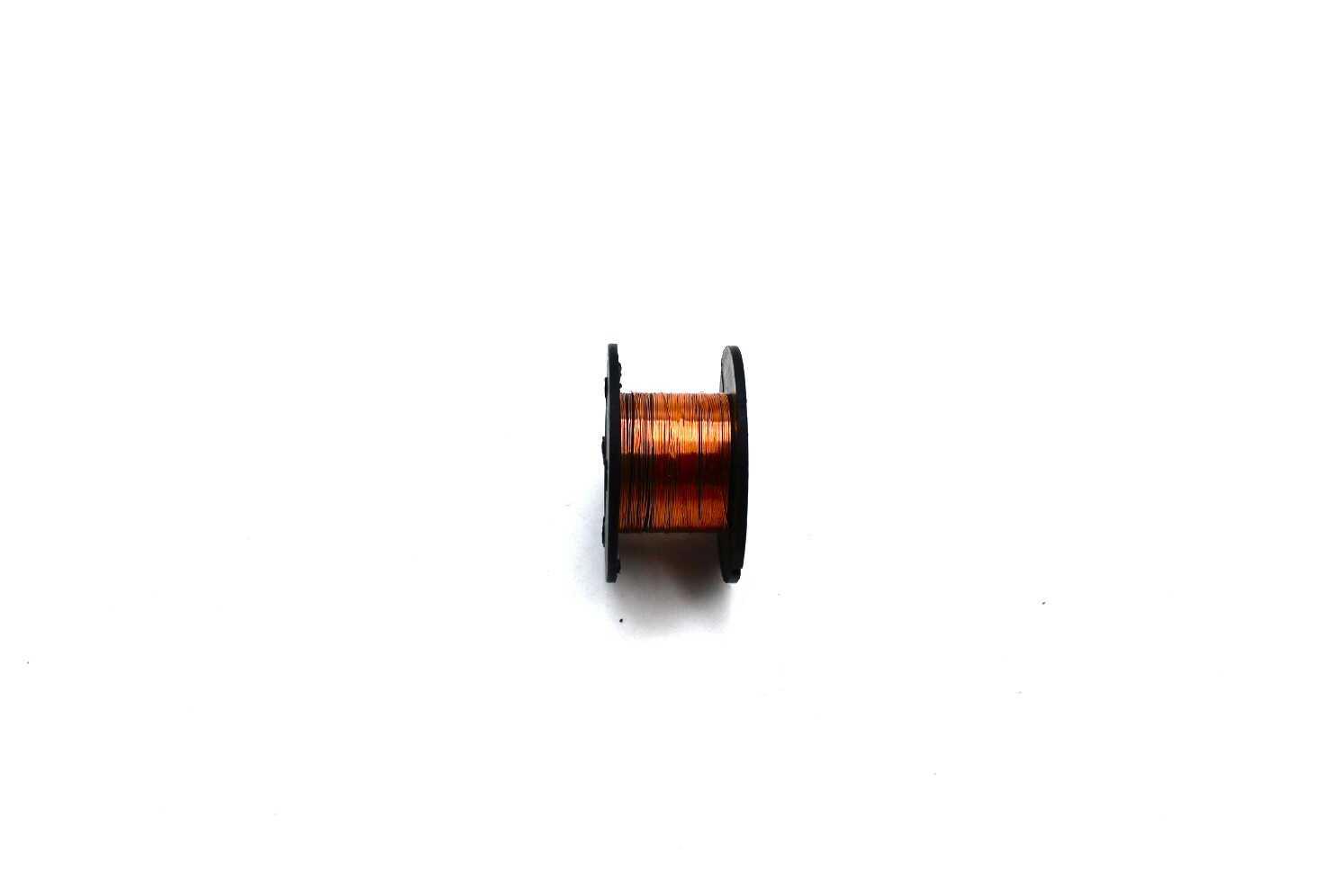
0.1MM Copper Soldering PPA Enamelled Repair Reel Wire
Ultra-fine magnet wire ideal for SMD rework and PCB trace repair. The 0.1mm gauge is perfect for bridging SMD pads and making fine connections.

6 Flexible Arms Soldering Station With Swiveling Alligator Clip
A helping hands station is essential for SMD work — hold your PCB firmly while you solder tiny components. Six arms give you maximum flexibility.
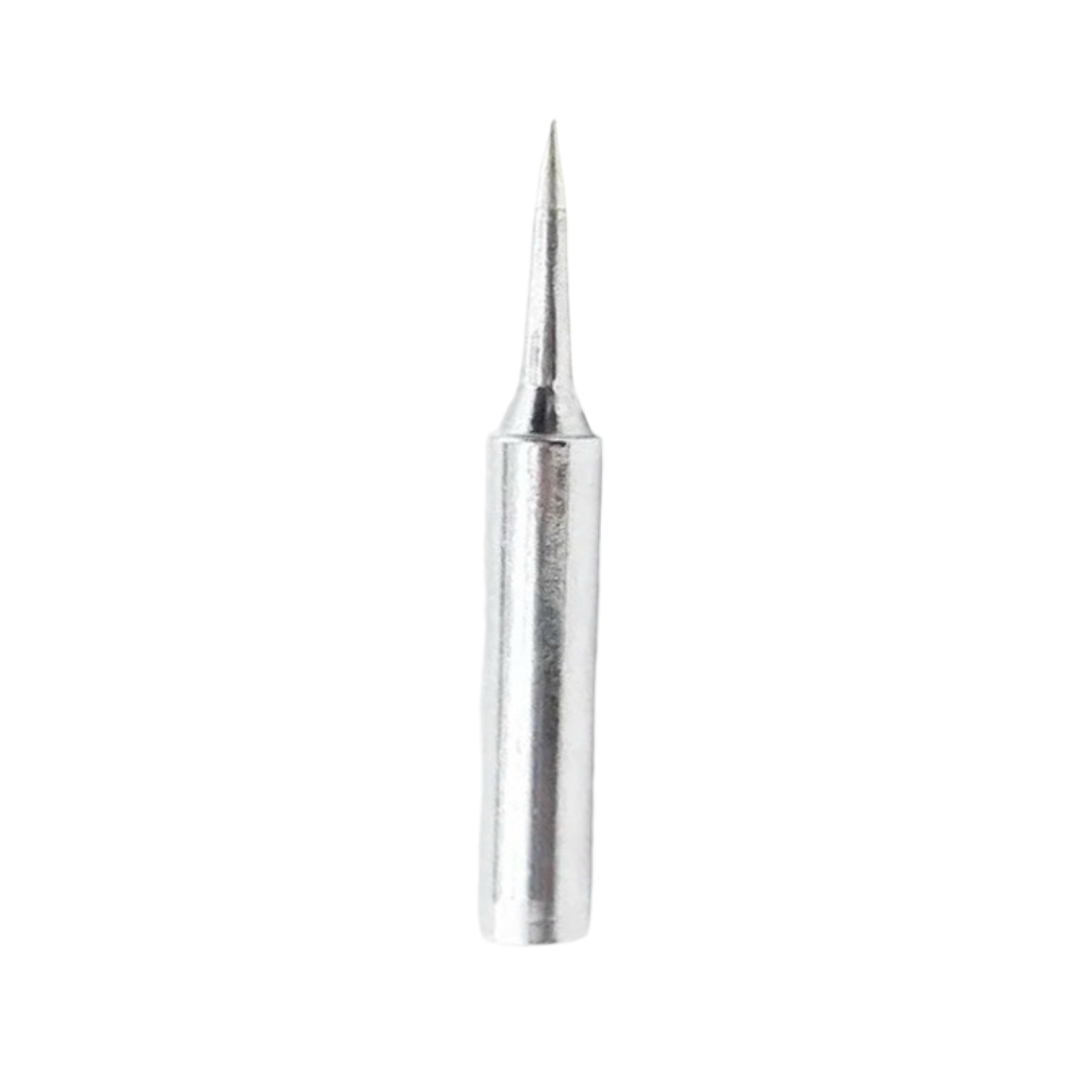
BAKON Soldering Iron Tip 900M-T-I
A fine-tip soldering iron tip is non-negotiable for SMD work. This BAKON tip provides excellent heat transfer with the precision needed for small pads.
Frequently Asked Questions
Q: Can I use SMD components on a breadboard?
A: Standard breadboards are designed for through-hole components. SMD components cannot be plugged directly into breadboard holes. However, SMD breakout boards/adapters (small PCBs that convert SMD pads to through-hole pin headers) allow you to use SMD components in breadboard prototyping. These are widely available for common SMD ICs and packages.
Q: What is the smallest SMD component I can realistically solder by hand?
A: Most experienced hobbyists can reliably solder 0603 components by hand with a good iron and magnification. Some experienced rework technicians can handle 0402. Anything smaller (0201 or below) practically requires hot air or reflow oven for reliable results.
Q: How do I read the value of an SMD resistor?
A: SMD resistors use a numeric code. 3-digit code: first two digits are significant figures, third digit is multiplier. Example: 103 = 10 × 10³ = 10kΩ. 4-digit code: first three are significant, last is multiplier. Example: 1002 = 100 × 10² = 10kΩ. Some use EIA-96 codes (letter + number) for 1% tolerance resistors. A component tester like the LCR-T4 can instantly measure any SMD resistor.
Q: Are SMD capacitors polarized?
A: Most SMD ceramic capacitors (in 0402, 0603, 0805 packages) are non-polarized and can be placed in any orientation. SMD electrolytic (aluminum) and tantalum capacitors are polarized — the positive terminal is typically marked. Tantalum capacitors have a stripe or dot indicating the positive end.
Q: What temperature should I use to solder SMD components?
A: For hand soldering SMD components with leaded solder, 300-320°C is typical. With lead-free solder, use 350-370°C. The key with SMD is speed — touch the pad and component lead simultaneously for 1-2 seconds maximum, then remove the iron. Prolonged heat will lift pads or damage components.


Add comment