
Standard RC servo motors (SG90, MG996) have built-in position feedback through an internal potentiometer. The servo driver electronics read this pot to hold the output shaft at the commanded angle. But what happens when you need to know — precisely and in real time — where the servo actually is? Or when you want to use a servo motor in a custom closed-loop system that goes beyond the standard PWM command protocol?
This tutorial covers two approaches to servo position feedback: reading the internal potentiometer (accessible with minor disassembly on standard servos) and adding an external optical or magnetic encoder to the output shaft. Both methods allow you to close the loop in your own control code, achieve sub-degree positioning, and detect mechanical stalls or slippage.
1. How Standard Servo Feedback Works Internally
Inside a standard RC servo (SG90, MG90S, MG996R) there are four key components:
- DC motor — a small brushed motor, typically 3–6 V
- Gearbox — reduces speed and increases torque (plastic for SG90, metal for MG996R)
- Potentiometer — a 5 kΩ linear pot connected mechanically to the output shaft. As the shaft rotates, the pot wiper moves
- Control PCB — receives the PWM signal (1–2 ms pulse width = 0–180°), reads the pot via ADC, runs a proportional error amplifier, and drives the motor accordingly
The internal pot is the servo’s position sensor. It typically rotates through about 120–180° of travel (matching the servo’s mechanical range). The wiper output sweeps from near-0 V at one extreme to near-VCC at the other. This is exactly what we can read to know the current servo position without any external components — if we can access the pot wiper pin.
2. Reading the Internal Potentiometer on Arduino
Accessing the Internal Pot
On most standard servos, the potentiometer has three connections: two rails (V+ and GND connected internally to the servo supply) and the wiper output. The wiper connects to the servo’s internal control PCB.
On the SG90: Opening the case reveals a small blue or black potentiometer. The wiper lead connects to the PCB via a short wire or direct PCB trace. You can solder a thin wire to the wiper terminal and route it out through a small notch in the case.
However, this modification requires disassembly and soldering on a tiny potentiometer — it is not practical for most beginners. The preferred approach is the external potentiometer method described next, which achieves the same result non-invasively.
When Internal Pot Reading Makes Sense
Internal pot reading is valuable when:
- You are building a custom servo controller from scratch (hacking the PCB)
- You need the most compact possible feedback (no external sensor)
- You are diagnosing why a servo does not reach its commanded position
3. External Potentiometer Feedback Method
The external potentiometer approach mounts a standard 10 kΩ potentiometer to the servo’s output shaft (or to the mechanical load it drives) and reads the wiper voltage with an Arduino analog input. This is the most common method for custom servo feedback loops.
Hardware Setup
A servo horn or disc mount connects the pot shaft to the servo output shaft. For the SG90, a small servo horn disc fits the output shaft directly. Epoxy or press-fit a 10 kΩ single-turn pot concentric with the servo output.
| Connection | Potentiometer Pin | Arduino |
|---|---|---|
| High end (CW limit) | Pin 1 | 5 V |
| Wiper (middle) | Pin 2 | A0 (analog input) |
| Low end (CCW limit) | Pin 3 | GND |
Basic Wiring Code
#include <Servo.h>

Servo myServo;
const int SERVO_PIN = 9;
const int POT_PIN = A0;

void setup() {
  Serial.begin(115200);
  myServo.attach(SERVO_PIN);
}

void loop() {
  // Read potentiometer
  int adcValue = analogRead(POT_PIN);  // 0–1023

  // Map to degrees (calibrate these end values after testing)
  float currentAngle = map(adcValue, 52, 971, 0, 180);
  currentAngle = constrain(currentAngle, 0, 180);

  Serial.print("Pot ADC: "); Serial.print(adcValue);
  Serial.print(" | Angle: "); Serial.println(currentAngle);

  delay(100);
}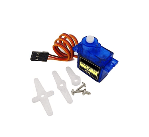
TowerPro SG90 180 Degree Rotation Servo Motor
The SG90 is the most popular servo for custom position feedback projects — lightweight, affordable, and its plastic case opens easily if you need to tap the internal potentiometer signal.
4. External Encoder Feedback Method
An external encoder provides higher resolution than a potentiometer and does not suffer from pot wear or noise. Two practical options exist for servo applications:
Magnetic Encoder (AS5048, AS5600)
These ICs use a small diametrically magnetised disc magnet mounted on the shaft and measure the absolute magnetic angle with 12-bit resolution (4096 positions per revolution). No mechanical wear, no noise, works with any shaft diameter, communicates via I2C or SPI. The AS5600 is widely available in India on small breakout boards and is an excellent choice for precision servo feedback.
AS5600 Wiring and Code
| AS5600 Pin | Arduino Pin |
|---|---|
| VCC | 3.3 V or 5 V |
| GND | GND |
| SDA | A4 (Uno/Nano) |
| SCL | A5 (Uno/Nano) |
| DIR | GND (sets rotation direction) |
#include <Wire.h>
#include <Servo.h>

#define AS5600_ADDR 0x36
#define ANGLE_REG_H 0x0E  // High byte of 12-bit angle

Servo myServo;
const int SERVO_PIN = 9;

float readAngle() {
  Wire.beginTransmission(AS5600_ADDR);
  Wire.write(ANGLE_REG_H);
  Wire.endTransmission(false);
  Wire.requestFrom(AS5600_ADDR, 2);

  if (Wire.available() >= 2) {
    int high = Wire.read();
    int low = Wire.read();
    int rawAngle = ((high & 0x0F) << 8) | low;  // 12-bit value 0–4095
    return rawAngle * (360.0 / 4096.0);  // Convert to degrees
  }
  return -1;  // Error
}

void setup() {
  Serial.begin(115200);
  Wire.begin();
  myServo.attach(SERVO_PIN);
}

void loop() {
  float angleDeg = readAngle();
  Serial.print("Angle: ");
  Serial.print(angleDeg, 2);
  Serial.println(" deg");
  delay(50);
}
The AS5600 gives 0.09° resolution — far better than a 10-bit ADC reading a potentiometer (0.18° best case) and immune to pot wear and contact noise.
Optical Incremental Encoder
Optical encoders (e.g., AMT102, HEDS series) mount to the servo’s rear shaft extension (if accessible). They output quadrature A/B signals that require interrupt-driven counting. They give relative position (not absolute) — you need a home position routine. Less convenient than AS5600 for servo applications but suitable if you already have an optical encoder on hand.
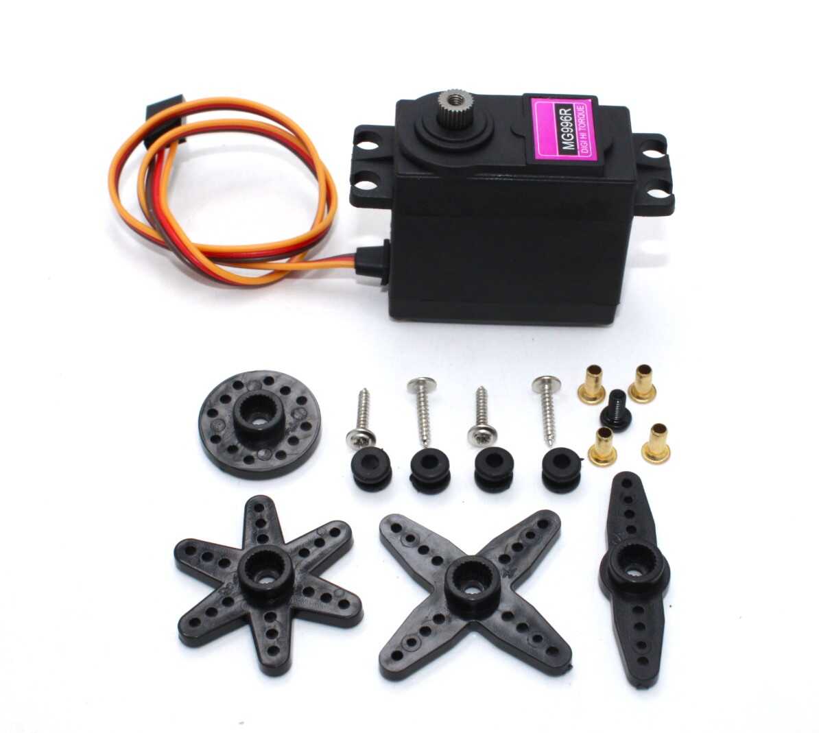
Servo MG996 13KG 180 Degree (High Quality)
The MG996 high-torque servo is ideal for robotic arm joints where external encoder or pot feedback is added for precise multi-turn position monitoring and stall detection.
5. Calibration: Mapping ADC Values to Degrees
Potentiometer calibration must be performed for each individual servo-pot combination because:
- Mechanical mounting never perfectly aligns 0° servo with 0° pot rotation
- Different servo brands have slightly different output shaft ranges
- Pot resistance end points may not align perfectly with 0 V and VCC
Two-Point Calibration Procedure
- Command the servo to 0° (
myServo.write(0)). Read the ADC value. Record as adc_min. - Command the servo to 180° (
myServo.write(180)). Read the ADC value. Record as adc_max. - Use these in the map function:
map(adcValue, adc_min, adc_max, 0, 180).
Multi-Point Calibration
For higher accuracy, measure ADC values at 0°, 45°, 90°, 135°, and 180°, then use linear interpolation between each segment. This corrects for non-linearity in both the pot and the servo’s mechanical response.
ADC Noise Reduction
Potentiometer readings have inherent noise from contact resistance variation and motor EMI. Average multiple readings to stabilise the output:
int readADCAverage(int pin, int samples = 8) {
  long sum = 0;
  for (int i = 0; i < samples; i++) {
    sum += analogRead(pin);
    delayMicroseconds(100);
  }
  return sum / samples;
}
6. PID Position Control with Feedback
The real power of position feedback is implementing your own position control — smoother, more tunable, and more precise than what the internal servo electronics provide:
#include <Servo.h>

Servo myServo;
const int SERVO_PIN = 9;
const int POT_PIN = A0;

// Calibrated from your measurements
const int ADC_MIN = 52;   // ADC at 0 degrees
const int ADC_MAX = 971;  // ADC at 180 degrees

float targetAngle = 90.0;
float Kp = 1.2;     // Adjust during tuning
float Ki = 0.05;
float Kd = 0.3;

float integral = 0;
float prevError = 0;

float getAngle() {
  int adc = readADCAverage(POT_PIN, 8);
  return (float)map(adc, ADC_MIN, ADC_MAX, 0, 180);
}

void runPID() {
  float currentAngle = getAngle();
  float error = targetAngle - currentAngle;

  integral += error;
  integral = constrain(integral, -100, 100);  // Anti-windup

  float derivative = error - prevError;
  prevError = error;

  float output = Kp * error + Ki * integral + Kd * derivative;

  // Convert PID output to servo command (center at 90)
  int servoCmd = (int)constrain(90 + output, 0, 180);
  myServo.write(servoCmd);

  Serial.print("Target: "); Serial.print(targetAngle);
  Serial.print(" | Actual: "); Serial.print(currentAngle, 1);
  Serial.print(" | Error: "); Serial.print(error, 1);
  Serial.print(" | Cmd: "); Serial.println(servoCmd);
}

void setup() {
  Serial.begin(115200);
  myServo.attach(SERVO_PIN);
}

void loop() {
  // Read target from Serial if sent
  if (Serial.available()) {
    targetAngle = Serial.parseFloat();
    targetAngle = constrain(targetAngle, 0, 180);
  }
  runPID();
  delay(20);  // 50 Hz control loop
}
7. Stall Detection and Protection
One of the most valuable uses of position feedback is detecting when a servo is mechanically stalled — commanded to an angle it cannot reach due to an obstruction. Sustained stall overheats the motor and can permanently damage the servo.
const float STALL_THRESHOLD_DEG = 3.0;  // Position error > 3° = stall
const unsigned long STALL_TIMEOUT_MS = 1000;  // Stall for 1 second = fault

float lastPosition = 0;
unsigned long stuckSince = 0;
bool stallFault = false;

void checkStall(float commanded, float actual) {
  float error = abs(commanded - actual);

  if (error > STALL_THRESHOLD_DEG) {
    if (stuckSince == 0) stuckSince = millis();
    if (millis() - stuckSince > STALL_TIMEOUT_MS) {
      stallFault = true;
      // Return servo to safe position, cut current or alert
      myServo.write(90);  // Move to neutral
      Serial.println("STALL FAULT: servo at neutral");
    }
  } else {
    stuckSince = 0;  // Reset timer when error clears
    stallFault = false;
  }
}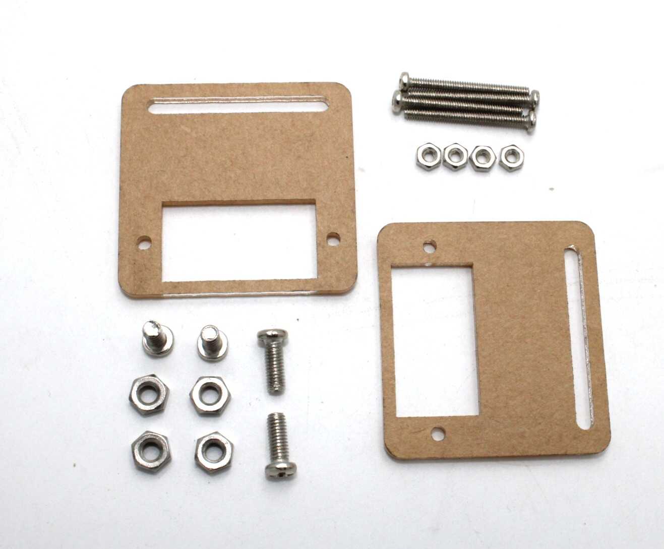
Servo Mount Holder Bracket for SG90/MG90 (Pack of 2)
Rigid mounting is essential when adding external potentiometers or encoders for position feedback — this bracket provides a stable, aligned mount for SG90 and MG90 servos.
8. Position Tracking for Continuous Rotation Servos
Continuous rotation servos have no internal position feedback (the internal pot is disconnected or removed). To add position tracking, mount a magnetic encoder (AS5600) or a multi-turn potentiometer on the output shaft. This enables you to command a specific number of rotations rather than a speed, effectively creating a geared DC motor with absolute position control.
For multi-turn tracking beyond 360°, use a quadrature encoder and count pulses cumulatively. The encoder gives relative position from the startup point. Add a home switch or index pulse for absolute position reference on power-up.
9. Multi-Servo Position Monitoring
For robotic arms with 3–6 servos, monitoring all positions simultaneously requires multiple analog inputs. Arduino Uno has 6 analog inputs (A0–A5), sufficient for a 5-DOF arm with one channel for a battery monitor.
To keep the control loop fast with multiple servos, use millis()-based timing rather than delay():
const int NUM_SERVOS = 5;
const int SERVO_PINS[] = {3, 5, 6, 9, 10};
const int POT_PINS[] = {A0, A1, A2, A3, A4};
Servo servos[NUM_SERVOS];
float targets[] = {90, 90, 90, 90, 90};

unsigned long lastLoop = 0;
const int LOOP_INTERVAL = 20;  // 50 Hz

void loop() {
  if (millis() - lastLoop >= LOOP_INTERVAL) {
    lastLoop = millis();
    for (int i = 0; i < NUM_SERVOS; i++) {
      // Run per-servo PID and stall detection here
      float actual = getAngleForChannel(i);
      // ... PID update ...
    }
  }
}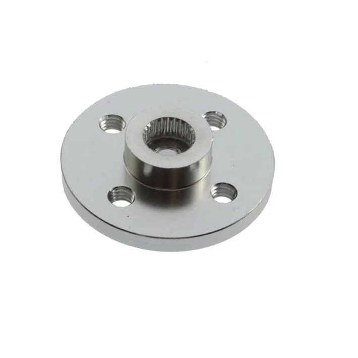
Aluminum Servo Horn/Arm 25T Round Type Disc MG995/MG996
When mounting an external potentiometer or encoder disc to a servo output shaft, the aluminum 25T servo horn provides a strong, accurate attachment point that resists rotation under load.
Frequently Asked Questions
Can I read the servo’s actual angle without adding any hardware?
Not reliably with standard RC servos — there is no feedback signal on the standard three-wire interface. Smart servo protocols (Dynamixel, Feetech SCS series, Herkulex) provide position telemetry over a half-duplex serial bus. For standard SG90/MG996 servos, you need a pot or encoder added externally, or internal pot access via disassembly.
What is the resolution of a 10 kΩ pot with Arduino’s ADC?
Arduino Uno/Nano has a 10-bit ADC (1024 steps) with 5 V reference. For a 180° servo: 180° / 1024 = 0.176° per step theoretically. In practice, ADC noise reduces this to about 0.5–1° effective resolution. The AS5600 encoder achieves 0.088° resolution.
Will adding an external pot affect servo performance?
Mechanically, the pot adds a small load to the output shaft. For light-duty servos (SG90), use the smallest pot you can find (6 mm or 9 mm diameter) to minimise friction. For MG996R class servos, the extra friction from a standard 16 mm pot is negligible. Electrically, the pot draws less than 1 mA from the 5 V supply — no measurable impact.
My pot feedback reads different values each time — how do I fix this?
Three common causes: (1) The pot shaft is slipping in its mount — use a set screw or epoxy. (2) ADC noise from motor EMI — add a 100 nF capacitor from the pot wiper pin to GND and keep pot signal wires away from motor leads. (3) Pot supply voltage fluctuates with motor load — power the pot from a separate, regulated 3.3 V reference.
Can I use position feedback to stop the servo in mid-rotation?
Yes — this is exactly what custom position control is designed for. Command a target angle, read the actual angle, and set servo PWM to neutral when actual ≈ target (within your deadband, e.g., ±1°). This allows you to stop at any intermediate angle, not just the servo’s endpoints.
What is the deadband in servo position feedback?
The deadband is the position error range where you do not apply any correction (to avoid continuous hunting/oscillation). Set it to slightly larger than your measurement noise — typically 1–3° for a pot-based system and 0.2–0.5° for a magnetic encoder. Too small a deadband causes the servo to continuously hunt for the exact position.
Conclusion
Servo position feedback transforms a standard RC servo from a blind position-command actuator into a sensor-equipped element of a closed-loop control system. The external potentiometer method is the most accessible starting point — requires only a 10 kΩ pot, three wires, and an Arduino analog pin. For higher resolution and long-term reliability, the AS5600 magnetic encoder provides professional-grade position sensing at an affordable price.
With position feedback in place, you unlock capabilities that no amount of open-loop servo commanding can achieve: real-time stall detection, sub-degree positioning accuracy, force/torque estimation from position lag, and fully customisable trajectory control. These are the building blocks of serious robotic arms, camera gimbals, and automated mechanical systems.
Shop servos and accessories at Zbotic: We stock SG90, MG90S, MG996R servos, servo mounts, extension wires, and aluminium horns for all your robotics projects. Visit zbotic.in/product-category/motors-drivers-pumps-actuators/ for fast delivery across India.


Add comment