
Table of Contents
- Introduction to Piezoelectric Vibration Sensing
- The Piezoelectric Effect Explained
- Piezo Sensor Modules vs Bare Elements
- Wiring to Arduino
- Reading Analog Output for Knock Intensity
- Digital Threshold Mode
- Advanced Knock Pattern Recognition
- Sensitivity and Mounting Tips
- Real-World Project Ideas
- Troubleshooting
- Frequently Asked Questions
Introduction to Piezoelectric Vibration Sensing
A piezoelectric vibration sensor — often simply called a piezo knock sensor or vibration disc — is one of the most elegant components in electronics. When you tap, knock, or vibrate it, it generates its own voltage without needing an external power supply for the sensing element itself. This self-generating property makes piezoelectric sensors incredibly useful for detecting physical impacts, surface vibrations, knocking patterns, and even audio-frequency vibrations.
In the Arduino world, piezo knock detection is a foundational technique used in everything from electronic drum pads to tamper detection systems, secret knock door locks, and industrial machine health monitoring. Unlike capacitive or resistive sensors, a piezo sensor does not drift with temperature or humidity, making it reliable in challenging environments.
This guide walks you through the complete process: from understanding the physics of the piezoelectric effect to writing Arduino code that recognises a specific knock pattern and triggers an action only when it matches.
The Piezoelectric Effect Explained
The word “piezo” comes from the Greek word for pressure. The piezoelectric effect describes a property of certain crystalline materials — most commonly quartz, barium titanate, and lead zirconate titanate (PZT) — to generate an electric charge in response to mechanical stress, and conversely, to deform mechanically when an electric field is applied.
In a piezo vibration sensor disc, a thin piezoelectric ceramic plate is bonded to a brass substrate. When you tap the disc, it bends slightly. This bending strains the ceramic layer, which responds by generating a voltage spike across its faces. The voltage amplitude is proportional to the force of the tap, and the frequency content mirrors the mechanical vibration frequency.
This voltage spike is typically in the range of 0.1V to over 5V for a firm knock, depending on the disc size and the force applied. On an Arduino Uno with a 10-bit ADC reading 0–5V, this translates to a reading from 20 to over 1023 — a wide dynamic range suitable for distinguishing light taps from hard strikes.
Important: Piezo Output Can Exceed Arduino Limits
A hard impact can drive a piezo disc to generate over 50V transiently. Always protect your Arduino’s analog pin with a voltage divider or a pair of protection diodes (clamping to 5V and GND). Most off-the-shelf piezo knock sensor modules already include this protection circuitry.
Piezo Sensor Modules vs Bare Elements
You have two choices when buying a piezo vibration sensor for Arduino projects:
Bare Piezo Disc
A naked piezo disc (typically 20mm or 27mm diameter) with two solder pads. You mount it directly onto a surface using double-sided tape or acoustic coupling gel. You need to add your own protection resistor (1 MΩ pull-down) and voltage clamping. Bare discs are cheaper and offer maximum sensitivity but require more careful circuit design.
Piezo Module Board
A small PCB carrying a piezo disc plus a comparator IC, an onboard threshold potentiometer, and both analog and digital output pins. This is the most convenient option for Arduino beginners. The digital output goes HIGH when vibration exceeds the set threshold; the analog output gives raw voltage for intensity measurement.
For knock pattern recognition, use the analog output. For simple knock/no-knock detection, the digital output is sufficient and requires no ADC.
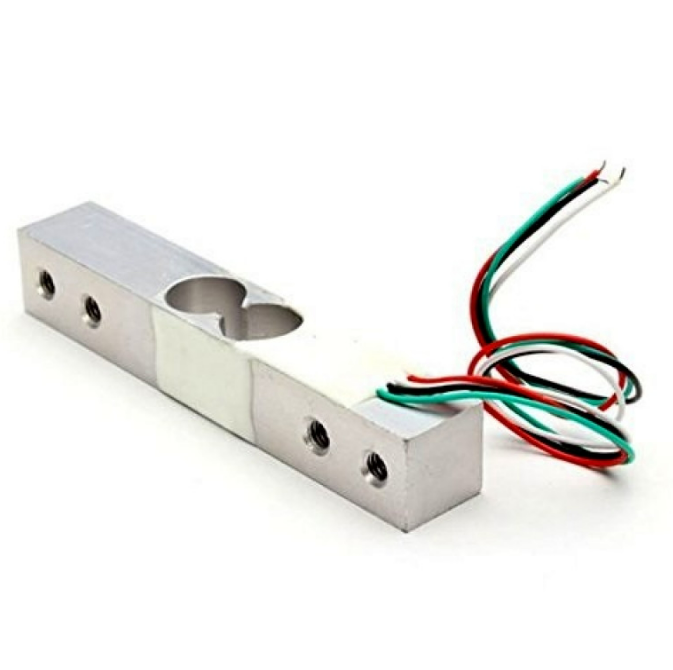
10Kg Load Cell — Electronic Weighing Scale Sensor
Need force rather than vibration? A load cell with HX711 measures sustained pressure — ideal when you need to distinguish a tap from a sustained press.
Wiring to Arduino
The exact wiring depends on whether you have a bare disc or a module board.
Bare Piezo Disc Wiring
Piezo (+) lead  →  Arduino A0
Piezo (-) lead  →  Arduino GND
1 MΩ resistor   →  Between A0 and GND (pull-down)

Optional protection:
1N4148 diode (anode→A0, cathode→5V)  // clamp upper voltage
1N4148 diode (anode→GND, cathode→A0) // clamp lower voltage
Module Board Wiring
Module VCC   →  Arduino 5V
Module GND   →  Arduino GND
Module AO    →  Arduino A0   (analog intensity)
Module DO    →  Arduino D2   (digital threshold output)
Reading Analog Output for Knock Intensity
The simplest useful sketch reads the analog pin and prints the ADC value whenever it crosses a noise floor threshold.
const int PIEZO_PIN = A0;
const int NOISE_FLOOR = 100; // Ignore ADC values below this

void setup() {
  Serial.begin(115200);
  Serial.println("Piezo vibration monitor ready.");
}

void loop() {
  int val = analogRead(PIEZO_PIN);

  if (val > NOISE_FLOOR) {
    Serial.print("Vibration intensity: ");
    Serial.println(val);
    delay(50); // Short debounce
  }
}
Open the Serial Plotter in the Arduino IDE (Tools → Serial Plotter) while tapping the sensor at different forces. You will immediately see the relationship between tap strength and ADC value. Use this data to calibrate your NOISE_FLOOR and impact thresholds for your specific mounting surface.
Digital Threshold Mode
For simple applications — a tamper alarm, a presence detector in a drawer, or a tilt-triggered counter — the module’s digital output is easier to use than the analog channel.
const int PIEZO_DO_PIN = 2;
const int BUZZER_PIN = 8;
bool lastState = LOW;

void setup() {
  pinMode(PIEZO_DO_PIN, INPUT);
  pinMode(BUZZER_PIN, OUTPUT);
  Serial.begin(9600);
}

void loop() {
  bool currentState = digitalRead(PIEZO_DO_PIN);

  if (currentState == HIGH && lastState == LOW) {
    Serial.println("Knock detected!");
    tone(BUZZER_PIN, 1000, 100); // 100ms beep at 1kHz
  }

  lastState = currentState;
  delay(10);
}
Adjust the potentiometer on the module board to set the sensitivity threshold for the digital output. Clockwise typically increases sensitivity (lower threshold); counter-clockwise reduces it.
Advanced Knock Pattern Recognition
The most impressive application of piezo knock sensors is a secret knock lock — a system that only unlocks when you knock the correct rhythm. Here is a complete implementation:
#include <Servo.h>

const int PIEZO_PIN = A0;
const int SERVO_PIN = 9;
const int LED_PIN = 13;

// Secret knock pattern: gaps between knocks in ms (relative)
// A gap stored as 0 means "start" (first knock)
const int SECRET_PATTERN[] = {0, 250, 500, 250, 750};
const int NUM_KNOCKS = 5;
const float TOLERANCE = 0.3;  // 30% timing tolerance
const int MAX_KNOCK_INTERVAL = 1500; // ms to wait between knocks
const int NOISE_FLOOR = 150;

Servo lockServo;
int knockTimes[10];
int knockCount = 0;
unsigned long lastKnockTime = 0;

bool checkPattern() {
  if (knockCount != NUM_KNOCKS) return false;

  // Calculate intervals between knocks
  int intervals[NUM_KNOCKS - 1];
  for (int i = 1; i < NUM_KNOCKS; i++) {
    intervals[i - 1] = knockTimes[i] - knockTimes[i - 1];
  }

  // Normalise against the expected pattern
  float scale = (float)intervals[0] / (float)(SECRET_PATTERN[1]);

  for (int i = 0; i < NUM_KNOCKS - 1; i++) {
    float expected = SECRET_PATTERN[i + 1] * scale;
    float ratio = (float)intervals[i] / expected;
    if (ratio  (1.0 + TOLERANCE)) {
      return false;
    }
  }
  return true;
}

void setup() {
  pinMode(LED_PIN, OUTPUT);
  lockServo.attach(SERVO_PIN);
  lockServo.write(0); // Locked position
  Serial.begin(9600);
  Serial.println("Secret knock lock ready.");
}

void loop() {
  int val = analogRead(PIEZO_PIN);
  unsigned long now = millis();

  // Check for timeout (sequence abandoned)
  if (knockCount > 0 && (now - lastKnockTime) > MAX_KNOCK_INTERVAL) {
    Serial.println("Sequence timeout — resetting.");
    knockCount = 0;
  }

  if (val > NOISE_FLOOR) {
    if (knockCount < 10) {
      knockTimes[knockCount] = now;
      knockCount++;
      lastKnockTime = now;
      Serial.print("Knock ");
      Serial.println(knockCount);
    }

    if (knockCount == NUM_KNOCKS) {
      delay(MAX_KNOCK_INTERVAL); // Wait to ensure sequence is complete
      if (checkPattern()) {
        Serial.println("Correct pattern! Unlocking...");
        lockServo.write(90); // Unlock
        digitalWrite(LED_PIN, HIGH);
        delay(5000); // Stay unlocked for 5s
        lockServo.write(0); // Re-lock
        digitalWrite(LED_PIN, LOW);
      } else {
        Serial.println("Wrong pattern.");
        // Flash LED to indicate failure
        for (int i = 0; i < 3; i++) {
          digitalWrite(LED_PIN, HIGH);
          delay(100);
          digitalWrite(LED_PIN, LOW);
          delay(100);
        }
      }
      knockCount = 0;
    }
    delay(100); // Debounce
  }
}
This pattern recogniser is scale-invariant: it measures the ratio of intervals rather than absolute timing, so the lock opens whether you knock slowly or quickly, as long as the rhythm is correct.
Sensitivity and Mounting Tips
Surface Coupling is Everything
A piezo disc taped loosely to a cardboard box will have completely different sensitivity than the same disc glued firmly to a wooden table. The better the acoustic coupling between the disc and the surface, the further away vibrations can originate and still be detected. Use cyanoacrylate (super glue) or double-sided mounting tape for the firmest coupling.
Orientation Does Not Matter Much
Unlike some sensors, piezo discs detect bending strain in any direction, so you do not need to worry about which face is up. However, mounting the disc so that it is free to flex (not clamped at the edges) maximises sensitivity.
Isolate from Low-Frequency Noise
In workshops or near machinery, low-frequency floor vibration can cause continuous triggering. Add a high-pass software filter in your code: only trigger on signals that peak within 5–50ms (typical knock duration). Sustained vibrations (machinery) will be filtered out while sharp impacts (knocks) still trigger correctly.
Mounting Locations by Application
| Application | Mount On | Sensitivity Setting |
|---|---|---|
| Door knock detector | Inner door panel, near centre | Medium-low |
| Electronic drum pad | Directly under drum head | Low (to handle hard hits) |
| Machine bearing monitor | Bearing housing surface | Maximum |
| Drawer tamper alarm | Drawer base panel | Medium-high |
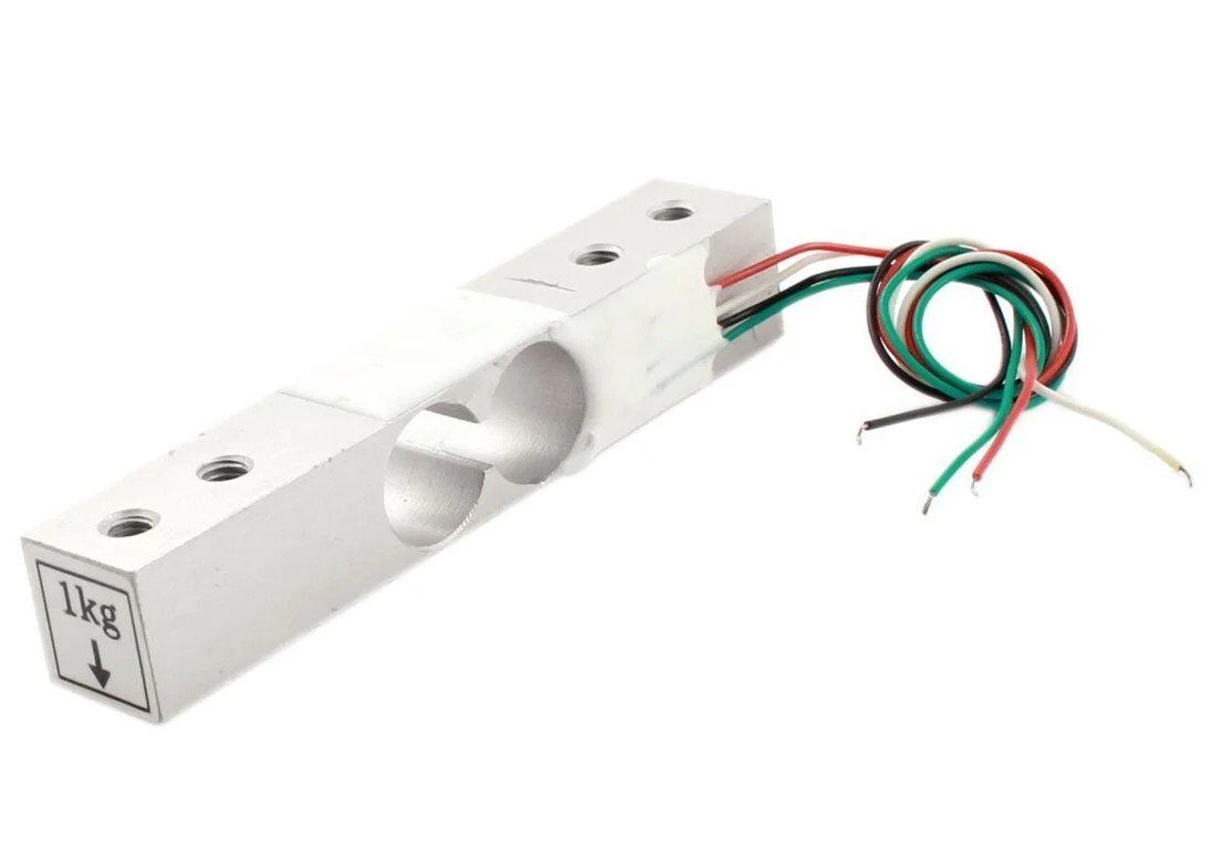
1Kg Load Cell — Electronic Weighing Scale Sensor
Pair with an HX711 amplifier and Arduino for precise force measurement — great for projects where you need to log the actual weight of an impact, not just detect it.
Real-World Project Ideas
1. Electronic Tabla or Drum Pad
Place piezo discs under each membrane of an Indian tabla or under foam drum pads. Route the analog outputs to multiple ADC channels. Use velocity-sensitive MIDI output: light tap → soft note, hard strike → loud note. A single Arduino Uno can handle 6 simultaneous channels using its A0–A5 pins, with a USB-MIDI library for direct computer interface.
2. Smart Package Tamper Detector
Glue a piezo disc inside a package or shipping box. Connect to a battery-powered ESP32 in deep sleep. Any knock or drop above a threshold wakes the ESP32, which logs the event timestamp and severity to SPIFFS and optionally sends an alert over Wi-Fi. When the package arrives, the recipient can audit the shock log to determine if it was mishandled.
3. Water Pipe Leak Detection
Clip a piezo disc against a metal water pipe using a hose clamp. Leaks in plastic or metal pipes create a characteristic hissing vibration that can be detected by monitoring the frequency content of the piezo signal using an FFT library. Normal water flow has a different spectral signature than a pressurised leak.
4. Mechanical Wear Monitoring for Motors
Mount a piezo disc on a motor housing or bearing bracket. As bearings wear, their vibration signature changes — both in amplitude and frequency. Log vibration levels over time. A sudden increase in average vibration amplitude is an early warning of bearing failure, allowing predictive maintenance before a breakdown occurs.
Troubleshooting
ADC Always Reads Maximum Value
The piezo disc is probably generating voltages above 5V. Add voltage clamping diodes between the analog pin and 5V/GND rails. If using a module, check that the onboard protection circuitry is intact. Also ensure the pull-down resistor (1 MΩ) is present — without it, the pin floats and reads maximum.
No Response to Tapping
Check that the disc is actually bonded to the measurement surface. A piezo disc sitting loosely on a table will not pick up vibration efficiently. Also verify the wire connections — piezo leads are delicate and easily broken at the solder joint.
Continuous False Triggers from Nearby Machinery
Implement a peak detection filter: only register a knock if the ADC value exceeds the threshold AND the previous reading was below the noise floor. This rejects sustained vibrations while still capturing sharp impacts.
Frequently Asked Questions
Do I need a resistor with a piezo vibration sensor?
Yes. Always use a 1 MΩ pull-down resistor between the signal pin and GND when using a bare piezo disc. Without it, the Arduino’s analog pin floats and reads noise. Module boards typically include this resistor on the PCB, but verify by checking the board schematic.
What is the difference between a piezo buzzer and a piezo vibration sensor?
They use the same piezoelectric element but in opposite ways. A buzzer drives the element with an AC voltage to produce sound (exploiting the converse piezoelectric effect). A sensor passively reads the voltage generated by mechanical deformation. Many makers use the same bare piezo disc for both purposes in different parts of their circuit — the same disc can buzz when driven and sense when monitored.
Can I detect vibration through a wall?
Yes, if the piezo disc is firmly coupled to the wall surface. Vibration travels as acoustic waves through solid materials, and a piezo disc bonded to a concrete or brick wall can detect knocks from the other side. The sensitivity drops with wall thickness and material damping, but it is entirely feasible for thin drywall partitions.
How sensitive is a piezo disc compared to an accelerometer?
A piezo disc is typically more sensitive to high-frequency vibration (above 100Hz) and very sharp impacts, but produces no DC output (it cannot measure steady-state inclination or slow tilts). An accelerometer can measure DC acceleration and is better for detecting low-frequency movement. For knock detection, the piezo disc wins. For tilt sensing or step counting, use an accelerometer.
What is the voltage output range of a typical piezo disc?
A 27mm piezo disc generates roughly 0.1V to 10V for taps, and can exceed 50V under hard impacts. The exact range depends on disc size, material, and bonding method. Always add voltage clamping protection to protect your microcontroller’s analog input from over-voltage damage.
Build your vibration sensing project today! Zbotic stocks piezo sensors, load cells, accelerometers, and all the passive components you need. Fast shipping across India. Explore Sensors at Zbotic →


Add comment