
Measuring rotational speed (RPM) is a fundamental requirement in motors, fans, industrial machinery, and hobby robotics. One of the most elegant and reliable methods uses a photointerrupter combined with a slotted encoder disk. This approach is cheap, non-contact, vibration-immune, and achieves excellent accuracy even at very high speeds. In this tutorial we will build a complete Arduino-based RPM meter using a photointerrupter, an encoder disk, and an optional OLED display — all components you can source from Zbotic.
nn
nn
1. How a Photointerrupter Works
n
A photointerrupter (also called an optical interrupter or fork sensor) consists of two elements in a U-shaped plastic body: an infrared LED on one arm and a phototransistor (or photodiode) on the other. When nothing is between them the IR beam passes freely and the phototransistor saturates, pulling the output LOW. When an opaque object (a disk slot wall) enters the gap, the beam is blocked, the phototransistor cuts off, and the output goes HIGH (with a pull-up resistor).
nn
This simple high/low transition is the pulse we count. Every time a slot in the encoder disk passes through the gap, we get two edges: one rising (slot enters), one falling (slot leaves). By counting pulses per unit time and knowing the number of slots on the disk, we can calculate RPM precisely.
nn
Common Photointerrupter ICs
n
- n
- H21A1 / H21B1 — classic slotted optocouplers, 2.5 mm gap, 30 mA LED
- EE-SX670 / EE-SX671 — Omron compact sensors with built-in schmitt trigger
- ITR9608 — popular, low-cost, direct NPN output, 3 mm gap width
- FC-03 module — pre-assembled with LM393 comparator and sensitivity pot, 5 V ready
n
n
n
n
n
The FC-03 module is the most popular choice for Arduino beginners because it provides a clean digital output directly without needing external pull-ups or comparators.
nn
2. Encoder Disk: Design and Types
n
The encoder disk (also called a slotted wheel or tachometer disk) is a circular disc with evenly-spaced slots (or holes) cut around its circumference. It mounts on the rotating shaft. As it spins through the photointerrupter gap, each slot creates one pulse.
nn
Slot Count Selection
n
More slots give higher resolution at low RPM but require faster interrupt handling at high RPM. As a guideline:
n
- n
- 1 slot: Simplest, one pulse per revolution. Easy to count but poor low-RPM resolution.
- 10–20 slots: Good balance for motors up to 5,000 RPM on Arduino.
- 60 slots: One pulse per degree — excellent for slow shafts or high accuracy.
- 100+ slots: Use only for very slow shafts; high-speed motors will overflow Arduino interrupt handling.
n
n
n
n
nn
Making Your Own Disk
n
You can print an encoder disk on paper and glue it to cardboard, or cut it from black PVC sheet. Many free online disk generators (search “optical encoder disk generator”) produce PDF files at any slot count and diameter. For a 20-slot disk, each slot is separated by 18°.
n
Standard encoder disks can also be 3D-printed in black PLA or purchased as metal stamped disks. Commercial disks ensure consistent slot width for even pulse duty cycle.
nn
3. Components List
n
- n
- Arduino Uno / Nano / Mega
- FC-03 photointerrupter speed sensor module (or bare ITR9608 + 10 kΩ pull-up)
- Encoder disk (20 slots recommended) matching shaft diameter
- 0.96″ I2C OLED display (SSD1306) — optional
- Jumper wires and breadboard
- USB cable and PC for programming
n
n
n
n
n
n
nn
4. Circuit Wiring
nn
FC-03 Module (with onboard LM393)
n
| FC-03 Pin | Arduino Pin | Notes |
|---|---|---|
| VCC | 5 V | Powers IR LED and LM393 |
| GND | GND | Common ground |
| D0 (digital out) | Pin 2 (INT0) | Hardware interrupt pin — critical for accuracy |
| A0 (analog out) | Not used | Raw analog signal, optional |
nn
Why use interrupt pin 2? RPM measurement requires counting every single pulse. Using digitalRead() in loop() will miss pulses at high RPM because the loop has other work to do. Hardware interrupts trigger immediately on every edge, regardless of what the CPU is doing.
nn
Mounting the Disk
n
Press-fit or glue the encoder disk onto the motor shaft. Position the photointerrupter so the disk slots pass cleanly through the sensor gap without touching either arm. Typical gap width is 3–5 mm; keep the disk edge well within the sensor’s active area.
nn
5. Arduino RPM Code with Interrupts
n
// RPM Meter using Photointerrupter + Encoder Diskn// Sensor output on Arduino Pin 2 (INT0)n// Encoder disk: 20 slotsnn#define SENSOR_PIN 2n#define SLOTS_PER_REV 20n#define SAMPLE_PERIOD 500 // ms — compute RPM every 500 msnnvolatile unsigned long pulseCount = 0;nunsigned long lastTime = 0;nfloat rpm = 0;nnvoid IRAM_ATTR pulseISR() {n pulseCount++;n}nnvoid setup() {n Serial.begin(115200);n pinMode(SENSOR_PIN, INPUT);n attachInterrupt(digitalPinToInterrupt(SENSOR_PIN),n pulseISR, RISING); // count each rising edgen lastTime = millis();n Serial.println("RPM Meter Ready");n}nnvoid loop() {n unsigned long now = millis();n if (now - lastTime >= SAMPLE_PERIOD) {n // Snapshot pulse count atomicallyn noInterrupts();n unsigned long count = pulseCount;n pulseCount = 0;n interrupts();nn // RPM = (pulses / slots) * (60000 / samplePeriodMs)n rpm = ((float)count / SLOTS_PER_REV) * (60000.0 / SAMPLE_PERIOD);nn Serial.print("RPM: ");n Serial.println(rpm, 1);n lastTime = now;n }n}nnn
The formula is straightforward:
n
RPM = (pulse_count / slots_per_revolution) × (60,000 / sample_period_ms)
nn
With a 20-slot disk and 500 ms sample period, a motor running at 3000 RPM generates 500 pulses in 500 ms — well within Arduino’s interrupt handling capacity.
nn
6. Adding an OLED Display
n
An OLED display makes the RPM meter self-contained and portable. Connect a 0.96″ SSD1306 I2C OLED to pins A4 (SDA) and A5 (SCL) on Arduino Uno/Nano:
n
#include <Wire.h>n#include <Adafruit_GFX.h>n#include <Adafruit_SSD1306.h>nn#define SCREEN_WIDTH 128n#define SCREEN_HEIGHT 64nAdafruit_SSD1306 display(SCREEN_WIDTH, SCREEN_HEIGHT, &Wire, -1);nn// ... (keep interrupt code from above) ...nnvoid setup() {n // ... (keep previous setup) ...n display.begin(SSD1306_SWITCHCAPVCC, 0x3C);n display.clearDisplay();n display.setTextSize(1);n display.setTextColor(WHITE);n display.println("RPM Meter");n display.display();n}nnvoid displayRPM(float r) {n display.clearDisplay();n display.setCursor(0, 0);n display.setTextSize(1);n display.println("Motor Speed:");n display.setCursor(0, 20);n display.setTextSize(3);n display.print((int)r);n display.setTextSize(1);n display.setCursor(100, 30);n display.println("RPM");n display.display();n}nnn
Call displayRPM(rpm) inside the if (now - lastTime >= SAMPLE_PERIOD) block after computing RPM.
nn
7. Improving Accuracy and Filtering
nn
Moving Average Filter
n
Raw RPM values fluctuate slightly due to motor speed variation and quantisation. Apply a simple moving average over 5 samples:
n
#define FILTER_SIZE 5nfloat rpmHistory[FILTER_SIZE] = {0};nint rpmIndex = 0;nnfloat filteredRPM(float newVal) {n rpmHistory[rpmIndex] = newVal;n rpmIndex = (rpmIndex + 1) % FILTER_SIZE;n float sum = 0;n for (int i = 0; i < FILTER_SIZE; i++) sum += rpmHistory[i];n return sum / FILTER_SIZE;n}nn
Debounce Considerations
n
Well-made encoder disks with clean edges do not need debouncing — the photointerrupter produces clean square wave transitions. If you see erratic counts, the issue is usually mechanical: the disk wobbles into the sensor gap (axial runout) or the slot edges are ragged. Fix mechanically rather than in software.
nn
Short Sample Periods
n
Using 100 ms sample periods gives faster response but coarser resolution. With a 20-slot disk at 300 RPM, you get only 10 pulses in 100 ms — limiting resolution to 10% of 300 = ±30 RPM steps. Use 500 ms or 1000 ms for better resolution at low RPM.
nn
8. Practical Applications
nn
Fan Speed Monitor
n
Computer fans typically have a tachometer pin (yellow wire) that generates 2 pulses per revolution. You can connect this directly to an interrupt pin and measure fan speed from 500 to 3000 RPM continuously.
nn
Motor Speed Controller
n
Combine the RPM meter with a PID library and a PWM motor driver. Set a target RPM; the PID controller adjusts PWM duty cycle to maintain it regardless of load. This is the foundation of every industrial motor drive.
nn
Bicycle Speedometer
n
Mount a single-magnet reed switch or photointerrupter on the fork and a magnet on the spoke. Measure RPM, multiply by wheel circumference, and display speed in km/h.
nn
Lathe / Drill Press RPM Gauge
n
Add an encoder disk to the spindle and mount the photointerrupter on the housing. Display real-time RPM on the OLED. Critical for woodworkers and machinists who need to match spindle speed to material and tool diameter.
nn
Turbine / Windmill Power Meter
n
Measure RPM of wind turbine blades, compute tip speed ratio, and estimate power output. Log data to SD card for analysis.
nn
9. Sensors from Zbotic
nn
A86 JSN-SR04T Waterproof Ultrasonic Rangefinder Module V3.0
Pair with your RPM project for complete machine monitoring — measure distance to moving parts alongside speed data.
nn
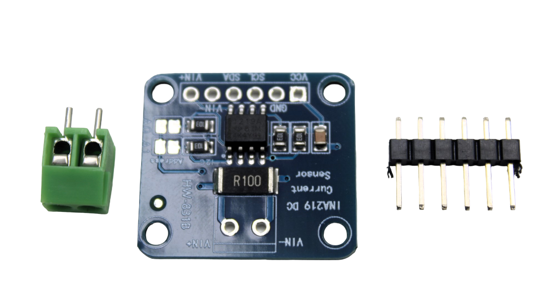
INA219 I2C Bi-directional Current/Power Monitoring Module
Monitor motor current consumption alongside RPM. Detect overloads: if RPM drops and current rises, the motor is stalling under load.
nn
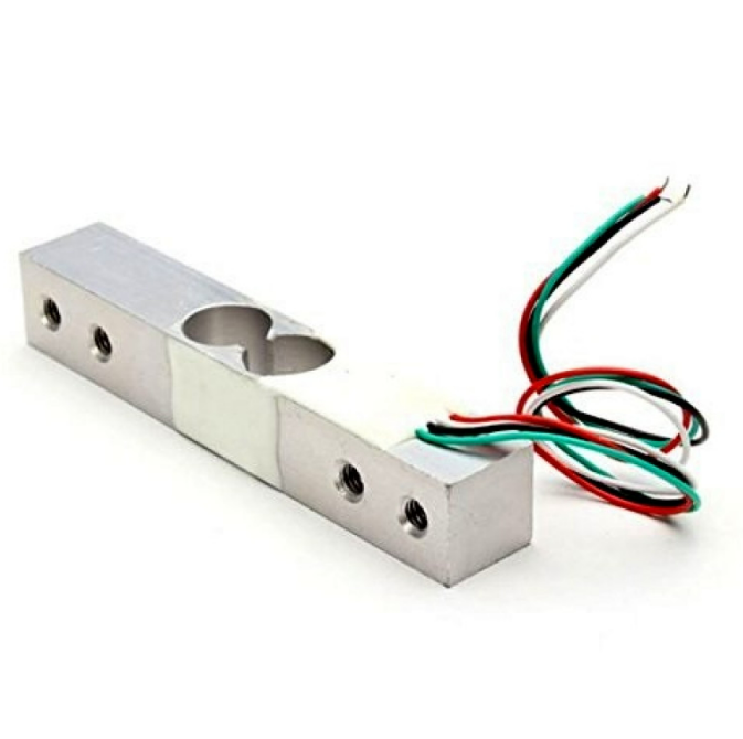
10Kg Load Cell — Electronic Weighing Scale Sensor
Add torque sensing by combining load cell readings with RPM data to compute mechanical power output (P = τ × ω).
nn
10. Frequently Asked Questions
nn
Q: What is the maximum RPM this circuit can measure?
n
With a 20-slot disk, Arduino Uno interrupt handling can comfortably count up to about 150,000 pulses per second, which equals 450,000 RPM — far beyond any real motor. In practice the limiting factor is the photointerrupter’s switching speed (~2–10 kHz typical for FC-03 modules) and the physical slot geometry. Most setups handle up to 30,000 RPM reliably.
nn
Q: Why do I get zero RPM readings even though the motor is spinning?
n
Check: (1) The encoder disk is actually passing through the sensor gap — not beside it. (2) The sensor is wired to an interrupt-capable pin (pins 2 and 3 on Uno/Nano). (3) The SLOTS_PER_REV constant matches your actual disk. (4) The FC-03 LED (green) is lit — confirming 5 V power is connected.
nn
Q: Can I use polling instead of interrupts?
n
For very low speeds (below ~100 RPM with a 20-slot disk) polling may work. At higher speeds, polling in loop() will miss pulses because the loop also runs display code, serial prints, etc. Always use hardware interrupts for reliable RPM measurement above 100 RPM.
nn
Q: My OLED shows 0 RPM at low speeds. Why?
n
At very low speeds there may be zero pulses within the sample period. With a 20-slot disk at 30 RPM you get 10 pulses per second — so in 500 ms you get only 5 pulses. This works fine. But if RPM drops below about 6 (one pulse per 500 ms sample), readings become erratic. For very low speeds, increase sample period to 2000 ms.
nn
Q: How do I make the encoder disk?
n
The easiest method: use an online encoder disk generator, print the PDF at 100% scale, laminate it, and cut it out. Alternatively, design one in FreeCAD and 3D-print it in black PLA. The disk colour does not matter as long as the slots are through-holes or clear windows against an opaque background.
nn
Build Your RPM Meter Today
n
Find photointerrupter modules, sensors, and all the components for your speed-measurement project at Zbotic — India’s trusted electronics store for makers and engineers.


Add comment