
If you have ever noticed your Arduino resetting when a motor starts, your sensor readings jumping erratically while a DC motor runs, or your radio-controlled vehicle’s receiver losing signal during throttle changes — you are experiencing DC motor electrical noise. This interference is produced by the brushes and commutator inside a DC motor and can wreak havoc on sensitive electronics if left unsuppressed.
The good news is that DC motor noise filtering with capacitors is cheap, simple, and highly effective. This guide explains the physics of motor noise, how to select the right capacitors, where to place them for maximum effect, and how to verify the fix is working.
Why DC Motors Generate Electrical Noise
Brushed DC motors generate electrical noise through two primary mechanisms: brush-commutator sparking and inductive load switching.
Brush-Commutator Sparking
Inside a brushed DC motor, carbon brushes press against a segmented copper commutator. As the motor rotates, the brushes make and break contact with commutator segments hundreds of times per second. Each make/break event creates a tiny arc. This arc is electrically equivalent to a very fast voltage pulse — a burst of electromagnetic energy that spans a wide frequency range from a few kilohertz up to several hundred megahertz.
This is why motor noise is described as broadband or wideband noise. It is not at a single frequency that you can block with a simple notch filter — it is spread across the entire radio frequency spectrum and can corrupt digital communication buses (I2C, SPI, UART), analog sensor readings, and even radio receivers.
Inductive Kickback
The motor windings are inductors. Whenever the current through an inductor changes suddenly — as happens during commutation — the inductor resists the change and generates a voltage spike. Without protection, these spikes can reach several times the supply voltage and can damage motor driver ICs and microcontroller GPIO pins.
This is why you should always use a flyback diode across a DC motor driver output. However, the diode handles only the low-frequency kickback — the high-frequency noise from brush arcing still requires capacitor suppression.
How Capacitors Suppress Motor Noise
A capacitor placed across (in parallel with) a noise source provides a low-impedance path for high-frequency noise currents. Instead of the noise current flowing through your circuit’s power rails, sensor wires, and ground planes — where it can cause interference — it circulates locally through the capacitor.
The capacitor’s impedance decreases as frequency increases: Z = 1/(2πfC). A 100nF capacitor has an impedance of about 16 Ohms at 100 kHz, but only 0.16 Ohms at 10 MHz. This means it effectively short-circuits high-frequency noise while barely affecting the DC motor current at near-zero frequency.
The three-capacitor network (one across the motor terminals plus one from each terminal to the motor casing/ground) is the standard technique used in virtually every commercial product that includes a brushed DC motor.
Which Capacitor Types to Use
Not all capacitors are equally effective for motor noise suppression. The key requirement is low ESR (Equivalent Series Resistance) and low ESL (Equivalent Series Inductance) at high frequencies.
Ceramic Capacitors (Recommended)
Ceramic capacitors are the best choice for motor noise filtering. They have very low ESR and ESL at high frequencies, they are small, cheap, and rated for high voltages relative to their size. Use X7R or X5R dielectric rated for at least twice your supply voltage (e.g., 50V ceramic caps for a 12V motor circuit). Avoid Y5V/Z5U ceramics as their capacitance drops dramatically with voltage and temperature.
Film Capacitors (Good Alternative)
Polyester (Mylar) and polypropylene film capacitors have low ESR and handle high-frequency noise well. They are larger than ceramics but more stable in capacitance value across temperature. Useful when you need higher capacitance values (above 1µF) for suppressing lower-frequency noise.
Electrolytic Capacitors (Supplementary Only)
Electrolytic capacitors have high ESL that limits their effectiveness above about 100 kHz. They are useful for bulk bypassing (reducing the impedance of the power supply at lower frequencies) but should always be combined with a ceramic cap in parallel for high-frequency filtering.
Avoid: Tantalum Capacitors Across Motor Terminals
Never use tantalum capacitors directly across motor terminals. The voltage spikes from motor commutation can exceed the capacitor’s voltage rating momentarily, and tantalum capacitors can fail catastrophically (short-circuit or fire) when over-voltage stressed.
Choosing the Right Capacitor Values
There is no single “correct” value for motor bypass capacitors — the optimal value depends on your motor speed, supply voltage, and the frequencies you need to suppress. However, the following values work well in the vast majority of robotics and embedded systems applications:
| Capacitor | Value | Placement | Suppresses |
|---|---|---|---|
| C1 | 100nF ceramic | Across motor terminals (M+ to M-) | Differential high-frequency noise |
| C2 | 10nF ceramic | Motor terminal 1 to motor case/chassis | Common-mode noise to ground |
| C3 | 10nF ceramic | Motor terminal 2 to motor case/chassis | Common-mode noise to ground |
| C4 (optional) | 10µF electrolytic | Across power supply rails near driver IC | Low-frequency supply fluctuations |
If you only have one capacitor available, place a 100nF ceramic directly across the motor terminals as close to the motor body as possible. This alone eliminates the majority of high-frequency brush noise. Adding the two 10nF caps to the motor case provides a significant additional improvement for very noise-sensitive applications (RF receivers, precision ADC measurements).
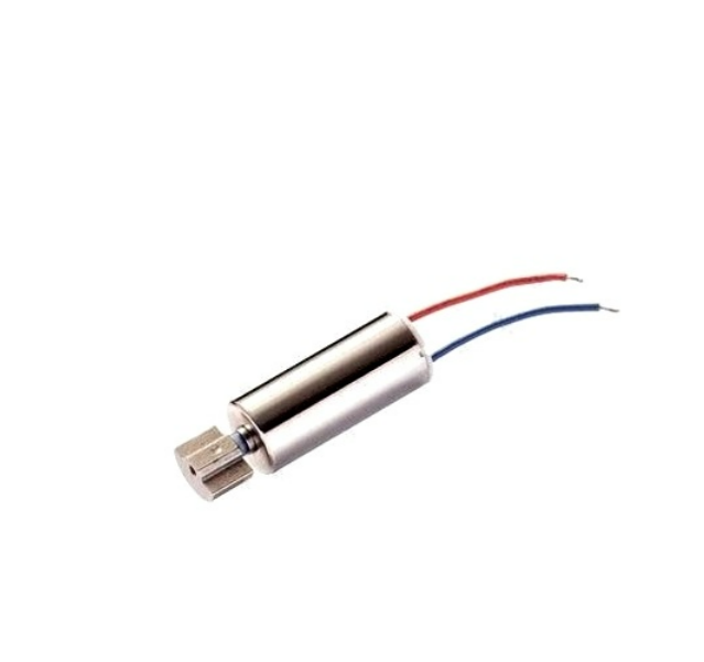
1.5–5V DC Vibration Motor with Wire
Small brushed DC motor commonly used in haptic feedback devices. Even tiny motors like this generate brush noise that benefits from capacitor suppression.
Capacitor Placement Guide
Placement is just as important as the capacitor value. A correctly sized capacitor placed too far from the noise source will be much less effective than a slightly wrong value placed correctly.
Golden Rule: Place Capacitors as Close to the Motor as Possible
The capacitor must be soldered directly to the motor terminals, or at most a few centimetres away. Every centimetre of wire between the motor and the capacitor adds inductance, which reduces the capacitor’s effectiveness at high frequencies. Ideal placement is to solder the capacitor leads directly onto the metal tabs of the motor — no extra wire, no PCB trace, just a direct solder joint.
Capacitor Across Motor Terminals
Solder a 100nF ceramic capacitor directly across the two motor terminal tabs. Bend the capacitor leads so that the body of the capacitor lies flat against the motor can. Use a hot soldering iron and keep the connection brief to avoid heat damage to the capacitor. This single capacitor dramatically reduces differential mode noise — the noise that appears between the two motor leads.
Capacitors from Each Terminal to Motor Case
For the two 10nF cap-to-case connections, you need to solder one lead to a motor terminal and the other to the metal motor body (the can). Clean the motor can with light sandpaper to expose bare metal, then use a small dab of solder. Some motors have a dedicated ground tab — use that if available. These capacitors suppress common-mode noise, which is noise that appears simultaneously on both motor leads with respect to the metal case.
Location on Your Circuit Board
In addition to the caps on the motor body, add a 100nF bypass capacitor on the PCB at the motor driver IC power input pins. This prevents the motor driver’s switching from disturbing other ICs that share the same power rail. Keep the trace from this capacitor to the IC power pin as short as possible.
Star Grounding
On battery-powered robots, use a star ground topology: all grounds converge at one point near the battery. Do not connect motor grounds and logic grounds at multiple points along a long wire, as this creates ground loops that act as antennas for motor noise.
Combining Capacitors with Ferrite Beads
For the most demanding noise suppression scenarios, combine capacitors with ferrite beads. A ferrite bead in series with the motor power leads (along with a capacitor to ground) forms an LC filter that is far more effective than capacitors alone.
Use a ferrite bead rated for your motor’s operating current (not stall current — the bead must not saturate at operating current). For a BO motor drawing 200 mA, a ferrite bead with 500 mA current rating is sufficient. For a larger motor at 2A, use a 3A rated ferrite bead.
The ferrite bead adds series impedance at high frequencies without resistive loss. Combined with a capacitor to ground, this forms a two-element low-pass filter that provides significantly more attenuation than the capacitor alone. This technique is used in commercial RC receivers, drone electronics, and automotive control modules where EMI requirements are strict.
PCB Layout Tips for Motor Noise Reduction
If you are designing a custom PCB that includes a DC motor driver, these layout practices will reduce motor noise reaching your sensitive circuitry:
- Separate power planes: Keep the motor supply (M+ / GND) and the logic supply (VCC / GND) as separate as possible on the PCB. If they share a ground plane, use a small series inductor or ferrite bead between the logic ground connection and the motor ground connection.
- Wide, short motor current traces: Motor current traces should be as short and wide as possible to minimise inductance. Thin, long traces act as antennas for motor noise.
- Bypass caps close to driver IC: Place 100nF and 10µF caps directly at the VCC and motor supply pins of your driver IC. Use vias directly from the capacitor pad to the power plane — do not route long traces first.
- Keep sensitive signals away from motor wires: Route I2C, SPI, ADC, and RF antenna traces as far as possible from motor current-carrying traces. Parallel routing of signal and motor current traces is particularly bad.
- Shield sensitive areas: Surround ADC reference inputs and analog sensor connections with a ground pour to provide shielding from noise coupling.
How to Test Whether Your Filtering Is Working
After adding capacitors, how do you confirm they are actually suppressing noise? Here are three practical testing methods for a home lab setting:
Method 1: Oscilloscope on Power Rail
Probe the VCC rail of your microcontroller or sensor while the motor runs. Without capacitors, you will see fast transients (spikes) riding on the DC supply voltage. After adding capacitors, these spikes should reduce in amplitude. A 10x reduction in spike amplitude is a good result.
Method 2: ADC Noise Test
Connect a potentiometer to an analog input and read 100 samples while the motor runs. Calculate the standard deviation of the readings. Before capacitor addition, you may see a standard deviation of 20–50 ADC counts. After, it should drop to 2–5 ADC counts or less on a 10-bit ADC.
Method 3: Radio Communication Range Test
If you are using an RC receiver or Bluetooth module, note the range or signal quality before and after adding capacitors. Even a small improvement in SNR can meaningfully increase reliable communication range. This is particularly important for indoor drone builds where the ESC noise can interfere with the RC receiver in the same frame.
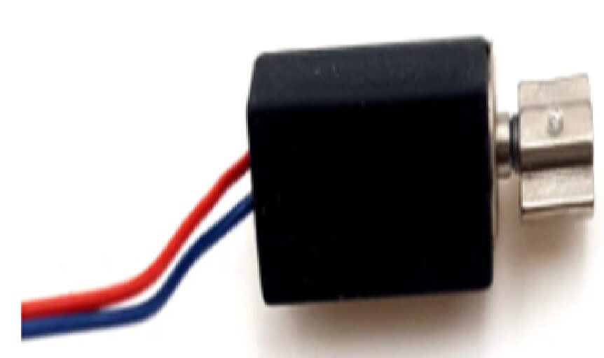
1.5V–3V 4×8mm Miniature DC Vibration Motor
Tiny brushed DC motor for haptics and notifications — add a 100nF cap across its terminals to prevent interference with nearby sensors and radios.
Special Cases: Brushless Motors, ESCs, and PWM Drivers
Brushless Motors (BLDC)
Brushless motors do not have brushes or commutators, so they do not generate brush-arcing noise. However, the ESC (Electronic Speed Controller) that drives them generates significant switching noise from its MOSFETs. The same capacitor techniques apply: add 100nF ceramics between each motor phase wire and the ESC housing ground, and add a bulk capacitor (100–470µF electrolytic) across the ESC battery input leads as close to the ESC as possible.
PWM Motor Drivers
When you drive a brushed motor with PWM (as you would with an Arduino and L298N), the switching frequency of the PWM adds to the motor’s own noise. Place 100nF caps close to the driver IC output pins. Increase the PWM frequency if your hardware allows it — most IC drivers work better at 20–30 kHz (above human hearing range) rather than the Arduino’s default 490 Hz, which can produce audible whining from the motor inductance.
High-Current Applications
For motors above 5A, ceramic bypass capacitors may not be adequate alone. Add a film capacitor (0.47µF–1µF) in parallel with the ceramic. The film cap handles slightly lower frequencies that the ceramic alone does not fully suppress.
Frequently Asked Questions
Q: What value capacitor should I use across a DC motor?
Start with a 100nF (0.1µF) X7R ceramic capacitor rated for at least twice your supply voltage. This handles the vast majority of brush noise in BO motors, gear motors, and small DC motors. Add two 10nF caps from each terminal to the motor case for further improvement.
Q: Can I use an electrolytic capacitor across a motor?
Electrolytic capacitors have high inductance and poor high-frequency performance. They are useful for low-frequency bulk bypassing at the power supply but should not replace ceramic caps for motor noise filtering. Always use a ceramic cap directly across the motor terminals.
Q: My Arduino resets when the motor starts. Will capacitors fix this?
Often yes, but the root cause may also be a power supply voltage drop. When a motor starts, it draws stall current (much higher than running current), which can cause the 5V supply to dip momentarily and reset the Arduino. Address both: add capacitors for noise, and add a large bulk capacitor (470µF electrolytic) across the 5V supply near the Arduino. Also consider powering the motor from a separate supply or battery.
Q: How do I solder a capacitor to a motor?
Tin both the capacitor leads and the motor terminal tabs with solder first. Then hold the capacitor against the terminals and touch the soldering iron briefly to the junction. Work quickly to avoid overheating the capacitor. The total soldering time for each joint should be under 3 seconds. After soldering, apply a small amount of hot glue or epoxy to mechanically secure the capacitor to the motor can so that vibration does not stress the solder joints.
Q: My brushless drone motors are causing receiver interference. What should I do?
For brushless motors and ESCs: add a 470µF low-ESR electrolytic capacitor (with a 100nF ceramic in parallel) directly across the ESC battery input leads within 5cm of the ESC. This is the most effective single fix for drone receiver interference. Also ensure the receiver antenna is routed away from motor and ESC wires.
Q: Do capacitors affect motor performance?
No. Bypass capacitors present negligible impedance at DC and low frequencies (motor operating frequency). They only affect high-frequency noise and do not measurably change motor speed, torque, or efficiency. There is no downside to adding properly rated bypass capacitors.
Working on a motor-powered electronics project? Browse Zbotic’s full range of DC motors, brushless motors, and motor accessories. Clean power means reliable electronics — and it starts with the right components. Shop motors at Zbotic.in with fast delivery across India.


Add comment