
MOSFET vs BJT: Power Switching Transistor Comparison
If you have ever built a motor driver, LED dimmer, or any power-control circuit, you have faced the classic dilemma: MOSFET vs BJT power switching transistor comparison. Both devices can switch or amplify current, but they work on fundamentally different principles and excel in very different situations. Whether you are a student in Pune building your first Arduino project or a professional engineer in Bengaluru designing a 10 A motor controller, choosing the wrong transistor type can mean wasted power, overheating, or outright circuit failure. This guide breaks down every important difference so you can make an informed choice every time.
How BJTs and MOSFETs Work
A Bipolar Junction Transistor (BJT) is a current-controlled device. A small base current (IB) controls a much larger collector current (IC). The ratio IC/IB is the DC current gain, commonly called hFE or β. A typical general-purpose NPN BJT like the BC547 has a β of 100–500, meaning a 1 mA base current can switch 100–500 mA through the collector. Because two types of charge carriers (electrons and holes) participate, BJTs are called bipolar.
A Metal-Oxide-Semiconductor Field-Effect Transistor (MOSFET) is a voltage-controlled device. Applying a voltage between the gate and source (VGS) creates an electric field that opens or closes a conduction channel. Because almost no current flows into the gate (it is insulated by a thin oxide layer), the driving circuit needs to supply virtually zero steady-state current. MOSFETs are unipolar — only one carrier type (electrons for N-channel, holes for P-channel) conducts.
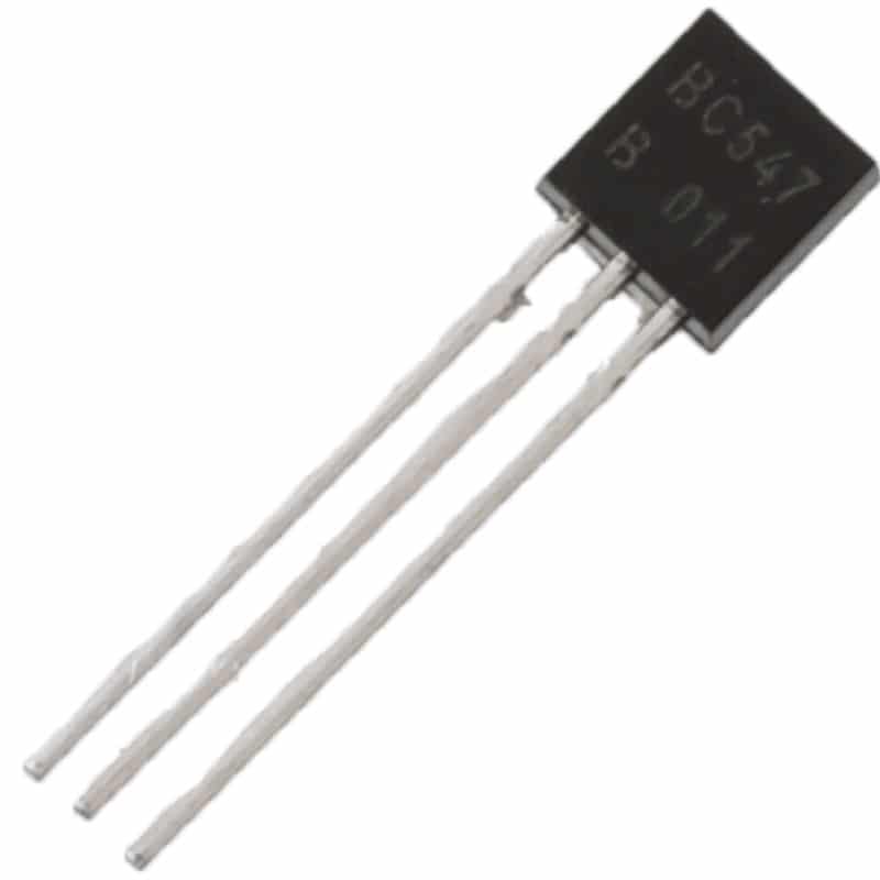
BC547 NPN 100mA Transistor TO-92 (Pack of 10)
A classic small-signal BJT perfect for understanding transistor switching basics. Great for logic-level switching, LED drivers, and audio pre-amplifier stages.
Key Electrical Parameters Compared
Understanding the spec-sheet numbers is crucial before you pick a transistor for your design.
| Parameter | BJT (e.g., 2N2222) | MOSFET (e.g., IRF540N) |
|---|---|---|
| Control type | Current (IB) | Voltage (VGS) |
| Input impedance | Low (kΩ range) | Very high (GΩ range) |
| On-state voltage drop | VCE(sat) ~0.2 V | I × RDS(on), can be <0.1 V |
| Switching speed | Slower (μs range) | Very fast (ns range) |
| Thermal runaway risk | High (VBE decreases with temp) | Low (RDS(on) increases with temp — self-limiting) |
| Cost | Very cheap (₹1–3 each) | Slightly higher (₹10–50 each) |
| Complexity | Simple drive circuit | Gate resistor needed; bootstrap for high-side |
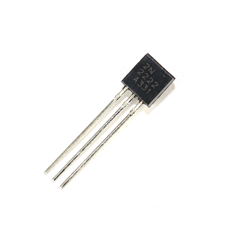
2N2222 NPN Transistor (Pack of 20)
A workhorse NPN BJT rated at 600 mA and 40 V. Ideal for relay drivers, small motor control, and signal switching in hobby circuits.
Switching Speed and Frequency Response
This is one area where MOSFETs win decisively. A BJT stores minority charge carriers in its base region when saturated. When you try to turn it off, you must first remove this stored charge — a process called storage time, which can add microseconds of delay. In PWM applications at 20 kHz or above (common in motor controllers and SMPS designs), this delay causes significant power loss and heat.
MOSFETs have no minority carrier storage. The gate capacitance (CGS and CGD) needs to be charged and discharged, but with a proper gate driver this happens in nanoseconds. SMPS converters, inverters, class-D audio amplifiers, and DC-DC converters operating at 100 kHz–1 MHz almost exclusively use MOSFETs or IGBTs for this reason.
Rule of thumb: For switching frequencies above 5 kHz with significant power, choose a MOSFET. Below 1 kHz with low power, a BJT is perfectly adequate and cheaper.
Gate / Base Drive Requirements
Driving a BJT requires a continuous base current equal to IC/β. For example, switching 1 A through an NPN with β = 100 requires 10 mA base current flowing continuously. A microcontroller GPIO pin can typically source only 20–40 mA, so a BJT works fine for small loads. For larger loads, you need a pre-driver transistor or dedicated driver IC.
Driving a MOSFET in steady state requires almost zero current — just a voltage above VGS(th) (typically 2–4 V for logic-level MOSFETs, 4–10 V for standard types). However, to switch fast, the gate capacitance must be charged quickly, which demands a brief current pulse. A GPIO can often drive a small MOSFET directly, but for large power MOSFETs or high switching frequencies, a dedicated gate driver IC (like IR2110 or TC4420) is recommended.
Important for Indian makers: Many Arduino projects use 5 V logic. Standard MOSFETs like IRF540N need VGS ≥ 10 V for full enhancement. Use logic-level MOSFETs (IRLZ44N, AO3400, etc.) that turn on fully at 4–5 V when interfacing directly with Arduino or ESP32 GPIO pins.
Thermal Performance and Power Dissipation
Power dissipation in a fully saturated BJT = VCE(sat) × IC. At 0.2 V and 5 A, that is 1 W — manageable with a small heatsink. But BJTs are prone to thermal runaway: as temperature rises, VBE decreases, allowing more base current, which raises IC, which raises temperature further. Parallel BJTs require emitter resistors to share current evenly.
Power dissipation in a MOSFET = ID² × RDS(on). At 10 A and RDS(on) = 0.05 Ω, that is only 5 W. Better yet, RDS(on) has a positive temperature coefficient — it increases with temperature, naturally limiting current. Multiple MOSFETs can be paralleled directly (though gate resistors are still recommended to prevent oscillation).

LCR-T4 Graphical Transistor Tester
Auto-identifies BJTs, MOSFETs, diodes, capacitors, and inductors. Displays β for BJTs and VGS(th) for MOSFETs — a must-have for every Indian electronics workbench.
When to Use a MOSFET vs a BJT
Choose a BJT when:
- Switching low power loads (<500 mA) at low frequencies (<1 kHz)
- Working in a linear amplifier where precise gain is needed
- Cost is the primary concern and speed does not matter
- Building audio amplifiers where bipolar characteristics give desirable linearity
- Interfacing with legacy circuits designed around BJT characteristics
Choose a MOSFET when:
- Switching heavy loads (motors, solenoids, high-power LEDs) above 1 A
- Operating at high switching frequencies (PWM motor control, SMPS, inverters)
- Driving from a microcontroller GPIO without a buffer stage (use logic-level MOSFETs)
- Paralleling multiple devices for very high current capacity
- Minimising power dissipation and heat generation is critical
Practical Circuit Tips for Indian Makers
Protecting your circuit: Always add a flyback diode (1N4007 or Schottky) across inductive loads (motors, relays, solenoids) regardless of whether you use a BJT or MOSFET. The MOSFET’s body diode provides some protection but is slow — an external fast diode is better for high-frequency PWM.
Gate resistor for MOSFETs: A 10–100 Ω gate resistor slows the transition slightly, reducing EMI and preventing oscillation caused by parasitic inductance. Do not omit it in any practical design.
Heatsinking: Both types need heatsinks for sustained high-power operation. Use thermal paste and proper mounting. The TO-220 package (common for both BJTs and MOSFETs) dissipates heat well with a clip-on heatsink.
Testing unknown transistors: Use an LCR-T4 or similar component tester to identify BJT vs MOSFET, determine pin order (CE/B or D/G/S), and measure β or VGS(th) before soldering. Many salvaged transistors are unlabelled or mislabelled.
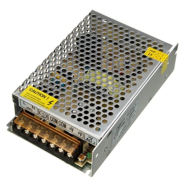
12V 10A SMPS – 120W DC Metal Power Supply
A reliable 120 W SMPS for powering your transistor switching experiments and high-current motor driver circuits. Metal enclosure for durability.
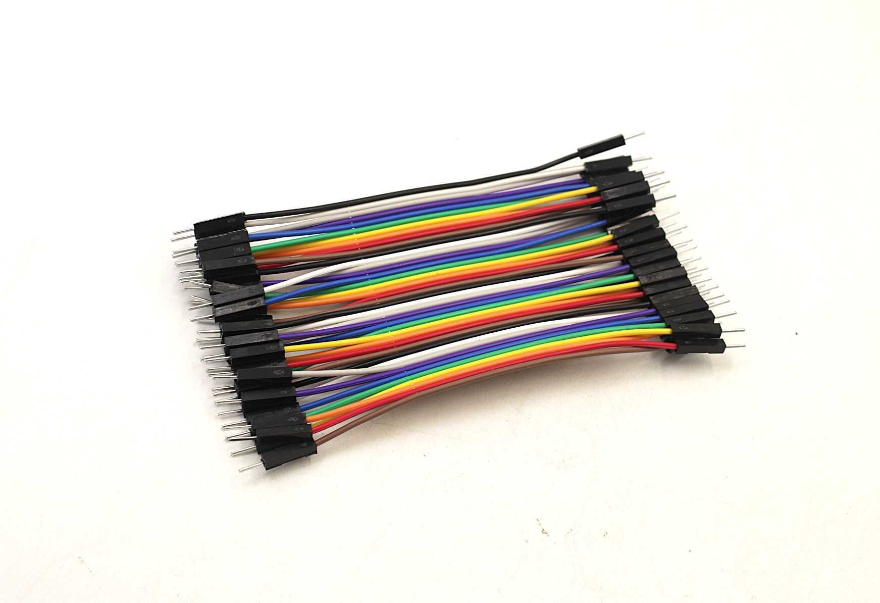
10CM Male To Male Breadboard Jumper Wires – 40Pcs
High-quality 2.54 mm pitch jumper wires for prototyping transistor switching circuits on a breadboard. Pack of 40 in multiple colours.
Frequently Asked Questions
Can I replace a BJT with a MOSFET directly in a circuit?
Not always. The pinouts differ (BJT: B/C/E vs MOSFET: G/D/S), and the drive requirements are completely different. A BJT base resistor value calculated for current limiting will not work as a MOSFET gate resistor (gate resistors are there to limit inrush current speed, not steady-state current). You will also need to adjust for the different threshold voltages and on-state voltage drops.
Which is better for an Arduino motor control project?
A logic-level N-channel MOSFET (like IRLZ44N) is generally better. Arduino GPIO outputs 5 V (or 3.3 V), which is enough to fully turn on a logic-level MOSFET. The MOSFET handles higher currents with less heat, and PWM at 490 Hz or higher is more efficient with a MOSFET.
Why do power supplies use MOSFETs and not BJTs?
SMPS (Switch Mode Power Supplies) operate at 50 kHz–500 kHz. BJT switching loss (due to storage time and saturation recovery) would be unacceptably high at these frequencies. MOSFETs switch in nanoseconds, making them ideal. IGBTs (a hybrid of BJT and MOSFET) are used in very high-power applications like inverter drives and EV motor controllers.
Is the 2N2222 a BJT or MOSFET?
The 2N2222 is a classic NPN BJT (Bipolar Junction Transistor). It has a maximum collector current of 600 mA and a VCE of 40 V, making it suitable for small signal switching and amplification.
What does VGS(th) mean for a MOSFET?
VGS(th) is the gate-source threshold voltage — the minimum VGS at which the MOSFET starts to conduct. However, at threshold the MOSFET is barely on. For full enhancement (minimum RDS(on)), you need VGS well above threshold — typically 10 V for standard types, or 4–5 V for logic-level types.
Ready to Start Switching?
Whether you choose a BJT or a MOSFET, Zbotic has the transistors, power supplies, and prototyping tools you need. From the classic BC547 BJT to high-current MOSFETs and breadboard-friendly jumper wires — everything is available with fast delivery across India.


Add comment