
Every robot arm you see — whether in a factory or on a YouTube build video — relies on a mathematical framework called kinematics. Understanding the kinematic model for a robot arm, both forward and inverse, is the essential bridge between mechanical assembly and controlled, programmable movement. This guide explains forward and inverse kinematics from first principles, shows you how to apply them to a servo-based 5-DOF arm, and gives you working code to bring it all to life.
What Is Kinematics in Robotics?
Kinematics is the study of motion without considering forces. In robotics, it answers two questions:
- Forward Kinematics (FK): Given the joint angles, where is the end-effector (gripper) in 3D space?
- Inverse Kinematics (IK): Given a target position in 3D space, what joint angles do I need to reach it?
FK is mathematically straightforward — multiply transformation matrices. IK is harder — multiple or infinite solutions may exist, and some targets are unreachable. Both are essential for a functional robot arm.
Understanding kinematics lets you programme your arm to follow trajectories (pick and place), interpolate smoothly between positions, and avoid joint limit violations. Without it, you’re just manually calibrating servo angles by trial and error — which doesn’t scale.
Degrees of Freedom and Joint Types
A degree of freedom (DOF) is one independent axis of motion. A 6-DOF arm can position its end-effector anywhere in 3D space with any orientation. Common DIY robot arms are 4–6 DOF.
Joint Types
- Revolute (R): Rotates around an axis. Most servo-driven joints are revolute. One DOF per joint.
- Prismatic (P): Slides along an axis (linear motion). Requires lead screws or linear actuators. Less common in DIY arms.
- Spherical: 3-DOF rotation like a ball joint. Complex to control mechanically.
For a typical 5-DOF servo arm: Base (rotation) → Shoulder (elevation) → Elbow (flex) → Wrist pitch → Wrist roll. Each is a revolute joint driven by one servo.

ACEBOTT ESP32 5-DOF Robot Arm Kit Expansion Pack
A complete 5-DOF servo robot arm expansion kit with ESP32 control. Perfect for applying forward and inverse kinematics concepts hands-on.
Forward Kinematics: Position from Joint Angles
Forward kinematics computes the end-effector position by chaining together transformations from the base frame through each link. Each transformation is a 4×4 homogeneous matrix that describes both rotation and translation.
For a 2D planar arm with two links (lengths L1 and L2) and joint angles θ1, θ2:
// 2-DOF planar forward kinematics
float L1 = 150.0; // mm
float L2 = 100.0; // mm

float theta1 = 45.0 * PI / 180.0; // radians
float theta2 = 30.0 * PI / 180.0;

float x = L1 * cos(theta1) + L2 * cos(theta1 + theta2);
float y = L1 * sin(theta1) + L2 * sin(theta1 + theta2);

// x and y are the end-effector coordinates
This extends to 3D by adding a z-component for each joint that moves out of the plane. For a full 3D arm, you need the Denavit-Hartenberg (DH) convention.
Denavit-Hartenberg Parameters Explained
The Denavit-Hartenberg (DH) convention is the standard method for systematically describing robot arm kinematics. Each link between joints is described by 4 parameters:
| Parameter | Symbol | Description |
|---|---|---|
| Link length | a | Distance along X from old Z to new Z |
| Link twist | α (alpha) | Angle from old Z to new Z around X |
| Joint offset | d | Distance along Z from old X to new X |
| Joint angle | θ (theta) | Angle from old X to new X around Z (variable for revolute joints) |
Each set of 4 DH parameters produces a 4×4 transformation matrix. Multiply all link matrices together to get the full transformation from the base frame to the end-effector — this is your FK solution.
DH Table Example: 3-DOF Arm
| Joint | a (mm) | α (°) | d (mm) | θ (variable) |
|---|---|---|---|---|
| 1 (Base) | 0 | 90° | 120 | θ1 |
| 2 (Shoulder) | 150 | 0° | 0 | θ2 |
| 3 (Elbow) | 100 | 0° | 0 | θ3 |

ACEBOTT ESP32 Programmable Robot Arm Kit – QD022
Beginner-friendly ESP32 robot arm kit with all servo hardware included. Ideal for learning and implementing FK/IK algorithms in a real build.
Inverse Kinematics: Angles from Target Position
Inverse kinematics is the harder problem: given a desired end-effector position (x, y, z), compute the joint angles (θ1, θ2, θ3 …) that achieve it. IK has several solution approaches:
Analytical (Closed-Form) IK
Works for arms with specific geometric properties (e.g., 3 revolute joints with parallel axes, or a spherical wrist). Fast, exact, and suitable for real-time control. Requires deriving the equations mathematically for your specific DH parameters.
Numerical IK (Jacobian Methods)
Iterative methods like the Jacobian pseudoinverse or Jacobian transpose converge to a solution numerically. More general but slower and can get stuck in local minima. Suitable for arms without a closed-form solution.
Cyclic Coordinate Descent (CCD)
A simple iterative algorithm that adjusts one joint at a time, each time minimising the distance to the target. Very easy to implement on microcontrollers and converges well for redundant arms.
Geometric IK for a 3-DOF Planar Arm
For a 3-DOF planar arm (all joints rotating in the same plane), geometric IK is the most practical approach. Given target position (x, y) and desired end-effector angle φ:
// 2-link planar IK (joints 2 and 3, with base rotation for x-y plane)
float L1 = 150.0; // upper arm length (mm)
float L2 = 100.0; // forearm length (mm)

float r = sqrt(x*x + y*y); // distance from shoulder to target

// Law of cosines for elbow angle
float cosTheta2 = (r*r - L1*L1 - L2*L2) / (2 * L1 * L2);
cosTheta2 = constrain(cosTheta2, -1.0, 1.0); // clamp for reachability
float theta2 = acos(cosTheta2); // elbow angle

// Two solutions: elbow-up and elbow-down
// Elbow-up (positive): theta2 as computed
// Elbow-down (negative): theta2 = -theta2

float alpha = atan2(y, x);
float beta = atan2(L2 * sin(theta2), L1 + L2 * cos(theta2));
float theta1 = alpha - beta; // shoulder angle

// Convert to degrees for servo
int servoShoulder = (int)(theta1 * 180.0 / PI);
int servoElbow = (int)(theta2 * 180.0 / PI);
Reachability check: If r > L1 + L2, the target is out of reach — fully extend the arm. If r < |L1 - L2|, the target is too close — move the base.
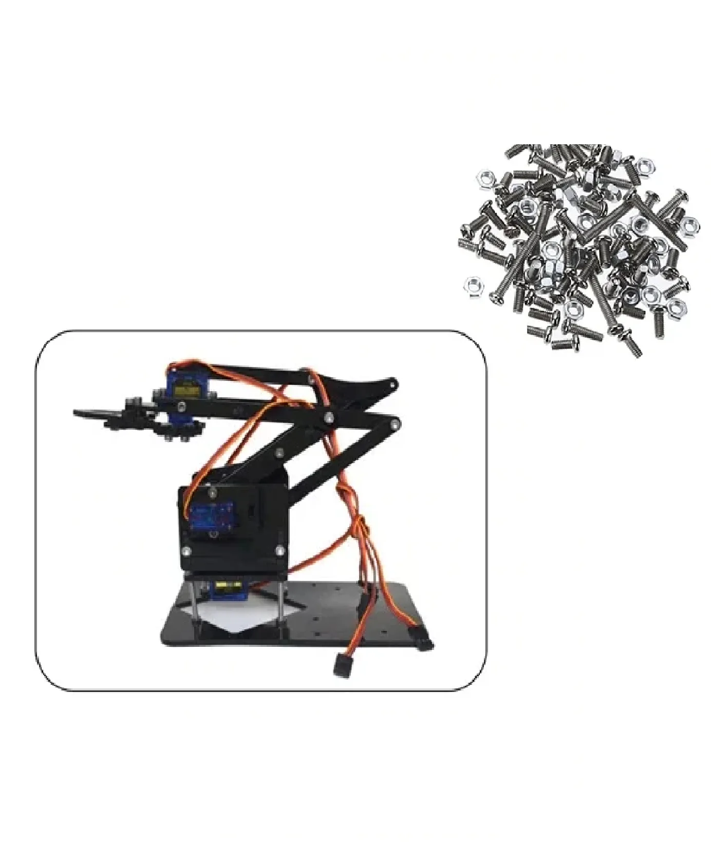
DIY Acrylic Robot Manipulator Mechanical Arm Kit
A full mechanical arm kit in acrylic — great for building and testing your forward/inverse kinematics code. Servo mounts and brackets included.
Arduino + Servo Code Implementation
Here is a minimal Arduino sketch that implements forward kinematics reporting and moves a 3-joint arm to a computed IK target:
#include <Servo.h>

Servo base, shoulder, elbow;
const float L1 = 150.0, L2 = 100.0;

void setup() {
  base.attach(9);
  shoulder.attach(10);
  elbow.attach(11);
  Serial.begin(9600);
}

void moveToXY(float x, float y, float baseAngle) {
  float r = sqrt(x*x + y*y);
  if (r > L1 + L2) r = L1 + L2; // clamp

  float cosE = (r*r - L1*L1 - L2*L2) / (2*L1*L2);
  cosE = constrain(cosE, -1.0, 1.0);
  float thetaE = acos(cosE);

  float alpha = atan2(y, x);
  float beta = atan2(L2*sin(thetaE), L1 + L2*cos(thetaE));
  float thetaS = alpha - beta;

  base.write((int)baseAngle);
  shoulder.write(90 + (int)(thetaS * 180.0 / PI));
  elbow.write(180 - (int)(thetaE * 180.0 / PI));

  Serial.print("Target: (");
  Serial.print(x); Serial.print(", ");
  Serial.print(y); Serial.println(")");
}

void loop() {
  moveToXY(100, 80, 90);  // Example: 90° base, reach (100, 80)
  delay(2000);
  moveToXY(180, 30, 45);  // Example: 45° base, reach (180, 30)
  delay(2000);
}
TowerPro SG90 180 Degree Rotation Servo Motor
The classic SG90 servo — lightweight, affordable, and perfect for 3–5 DOF robot arm joints. Widely used in DIY arm builds across India.
Smooth Trajectory Interpolation
Rather than jumping instantly between positions, interpolate joint angles linearly in small steps:
void interpolateTo(int targetBase, int targetShoulder, int targetElbow, int steps, int delayMs) {
  int startBase = base.read();
  int startShoulder = shoulder.read();
  int startElbow = elbow.read();

  for (int i = 1; i <= steps; i++) {
    float t = (float)i / steps;
    base.write(startBase + (int)(t * (targetBase - startBase)));
    shoulder.write(startShoulder + (int)(t * (targetShoulder - startShoulder)));
    elbow.write(startElbow + (int)(t * (targetElbow - startElbow)));
    delay(delayMs);
  }
}
Servo Mount Holder Bracket for SG90/MG90 (Pack of 2)
Sturdy servo mounting brackets for building robot arm joints. Compatible with SG90 and MG90 servos — sold in packs of 2.
Frequently Asked Questions
What is the difference between forward and inverse kinematics?
Forward kinematics calculates the end-effector position given joint angles. Inverse kinematics does the opposite — it finds the joint angles needed to reach a given position. FK is computationally simple; IK is harder and may have multiple or no solutions.
How many DOF do I need for a pick-and-place robot arm?
A minimum of 4 DOF is needed for basic 3D pick-and-place: base rotation, shoulder, elbow, and wrist pitch. 5 or 6 DOF adds wrist roll and orientation control, which is important for handling objects in different orientations.
Can I implement inverse kinematics on an Arduino?
Yes. Closed-form geometric IK for a 2–3 DOF planar arm runs comfortably on an Arduino Uno. For 5–6 DOF with real-time Jacobian IK, you may need an Arduino Mega, ESP32, or off-board computation via serial from a Raspberry Pi.
What is a singularity in robot kinematics?
A singularity is a configuration where the robot arm loses one or more DOF — multiple joint configurations map to the same end-effector position, or the arm is fully extended. Near singularities, joint speeds become infinite for small end-effector movements. Detect and avoid these during trajectory planning.
What is the workspace of a robot arm?
The workspace is the set of all positions the end-effector can physically reach. For a 2-link arm with lengths L1 and L2, the workspace is an annulus (donut shape) with outer radius L1+L2 and inner radius |L1-L2|. Joint angle limits further restrict the reachable workspace.
Build Your Own Robot Arm with Zbotic
From SG90 servos and mounting brackets to complete 5-DOF arm kits with ESP32 control boards, Zbotic has everything you need to start your robot arm kinematics journey. Fast delivery across India — order today and start building.


Add comment