
Inductor in AC Circuits: Inductive Reactance Tutorial
While capacitors often steal the spotlight in electronics education, the inductor in AC circuits is equally fundamental and offers complementary behaviour that enables a whole class of circuits impossible without it. From RF chokes to audio crossover networks, from DC-DC converters to resonant tank circuits, inductors are everywhere. Yet many students struggle with inductor behaviour because it’s less intuitive than resistors or capacitors. This guide demystifies inductive reactance, explains the voltage-current phase relationship, walks through RL circuit analysis, and connects the theory to practical designs you can build today.
Inductor Basics: What Is an Inductor?
An inductor is a passive component — typically a coil of wire wound around a core (air, ferrite, iron, or other magnetic material) — that stores energy in a magnetic field when current flows through it. The defining property is inductance (L), measured in Henries (H), which quantifies how strongly the coil resists changes in current.
Faraday’s law of electromagnetic induction underlies inductor behaviour: any change in current through the coil creates a changing magnetic flux, which induces a voltage (EMF) that opposes the change. This self-opposition is described by:
v(t) = L × di/dt
The induced voltage is proportional to the inductance L and the rate of change of current, not the current itself. This fundamental relationship explains all inductor behaviour in AC circuits:
- For DC (constant current, di/dt = 0): v = 0, so an ideal inductor is a short circuit for DC
- For AC (continuously changing current): v ≠ 0, so the inductor opposes current changes — creating opposition to AC that increases with frequency
- Rapid current changes (high frequency): inductor produces large opposing voltage — high impedance
Types of Inductors You’ll Encounter
- Air-core inductors: Low inductance (nH to µH), no core saturation, used at RF frequencies. Wind your own with enamelled copper wire.
- Ferrite-core inductors: Higher inductance (µH to mH), compact, used in RF chokes and switching converters
- Iron-core inductors (chokes): Very high inductance (mH to H), used at power/audio frequencies in mains filters and crossovers
- Toroidal inductors: Low leakage flux, ideal for high-efficiency power electronics

0.1MM Copper Soldering PPA Enamelled Repair Reel Wire
Wind your own inductors for LC oscillators and RF filters with this enamelled copper wire. The thin 0.1mm gauge is perfect for small ferrite-core toroids used in the MHz frequency range.
Inductive Reactance (XL): The Formula
Inductive reactance (symbol: XL) is the opposition offered by an inductor to AC current flow. Like capacitive reactance, it is measured in ohms, but it behaves in the exact opposite way with frequency:
XL = 2πfL = ωL
Where:
- XL = Inductive reactance in ohms (Ω)
- f = Frequency in Hertz (Hz)
- L = Inductance in Henries (H)
- ω = 2πf = angular frequency in radians per second
Key Observations
- XL increases with frequency: Higher frequency → more opposition. This is opposite to a capacitor.
- At DC (f = 0): XL = 0 — ideal inductor is a short circuit (zero opposition)
- At very high frequencies: XL → ∞ — inductor approaches an open circuit
- XL increases with inductance: A larger coil offers more opposition at the same frequency
Reactance Comparison: Capacitor vs Inductor
| Frequency | XL for 100µH | Xc for 100nF | Dominant Element |
|---|---|---|---|
| 1 kHz | 0.63 Ω | 1,592 Ω | Capacitor (high Xc) |
| 10 kHz | 6.28 Ω | 159 Ω | Capacitor still dominant |
| 159 kHz | 100 Ω | 10 Ω | Inductor dominant — resonance nearby |
| 1 MHz | 628 Ω | 1.59 Ω | Inductor (high XL) |
The frequency at which XL = Xc is the resonant frequency — more on this in our LC resonance guide.
Phase Relationship: Voltage Leads Current
The phase relationship in a purely inductive circuit is the mirror image of a capacitor:
Voltage LEADS Current by 90°
Recall the memory aid “CIVIL”: In an inductor (L), Voltage (V) leads Current (I) by 90°.
Mathematical Proof
If the current through the inductor is i(t) = I_peak × sin(ωt), then using v = L × di/dt:
v(t) = L × d/dt[I_peak × sin(ωt)]
v(t) = L × I_peak × ω × cos(ωt)
v(t) = I_peak × ωL × sin(ωt + 90°)
v(t) = V_peak × sin(ωt + 90°)
The voltage waveform leads the current waveform by 90°. Physically: the voltage must build up the magnetic field first, and then current can flow — voltage precedes current.
Power in a Purely Inductive Circuit
Like the capacitor, an ideal inductor dissipates zero average power. Energy stored in the magnetic field during the first quarter cycle is fully returned to the source during the next quarter cycle. Real inductors have winding resistance (DCR) that does dissipate power, described by the Q factor:
Q = XL / R_winding = ωL / R
Higher Q = lower losses = more ideal inductor behaviour. RF-grade inductors typically have Q > 50; audio chokes may have Q as low as 5–10.
RL Impedance in Complex Form
The impedance of an inductor in complex notation is:
Z_L = +j × XL = j × ωL
The positive imaginary value reflects that voltage leads current (opposite sign to capacitor’s −jXc).
Series RL Circuit Impedance
Z_RL = R + jXL = R + jωL
|Z_RL| = √(R² + XL²)
Phase angle θ = +arctan(XL / R)
Example: R = 1kΩ, L = 100 mH, f = 2 kHz
XL = 2π × 2000 × 0.1 = 1257 Ω
|Z| = √(1000² + 1257²) = √(1 × 10⁶ + 1.58 × 10⁶) = 1606 Ω
θ = arctan(1257 / 1000) = 51.5°
The voltage leads the current by 51.5° — between 0° (pure resistor) and 90° (pure inductor).
Series and Parallel RL Circuits
Series RL: Voltage Divider Effect
In a series RL circuit with AC input, the voltage divides between R and L. At frequencies where XL >> R, most voltage appears across the inductor. At frequencies where XL << R, most voltage appears across the resistor. This gives us:
- High-pass RL filter: Output taken across the inductor → passes high frequencies, attenuates low frequencies. Corner frequency: f_c = R/(2πL)
- Low-pass RL filter: Output taken across the resistor → passes low frequencies, attenuates high frequencies. Same corner frequency.
RL Corner Frequency Formula
f_c = R / (2πL)
Note: This is the inverse of the RC formula (f_c = 1/2πRC). For RL filters, increasing R or decreasing L raises the cut-off frequency.
RL Time Constant
The RL time constant τ = L/R (in seconds) determines how quickly current builds up in an RL circuit after a step voltage is applied:
i(t) = (V/R) × (1 − e^(−t/τ))
After one time constant, current reaches 63.2% of its final value V/R. After 5τ, it’s essentially at full current. This is why switching power supplies need time to ramp up — the output inductor’s time constant limits current slew rate.
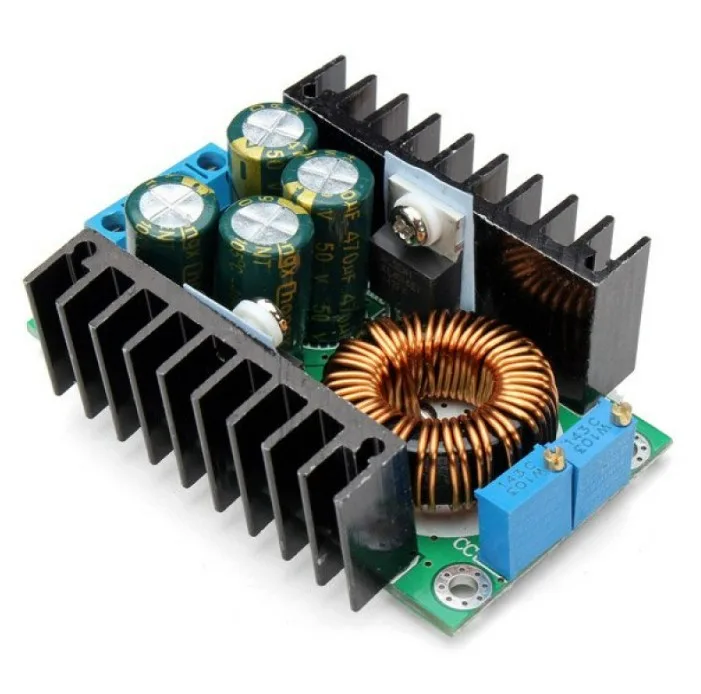
300W 10A DC-DC Step-down Buck Converter Module
Buck converters use an inductor as the core energy storage element — the inductor’s opposition to rapid current change (v = L×di/dt) is what allows efficient DC-DC conversion. Study this module to see inductors in action.
Practical Inductor Applications
1. RF Chokes (Bias Tees)
An RF choke is an inductor placed in the DC supply line of an RF amplifier. Its high impedance at RF frequencies (XL = 2πfL) blocks RF from entering the DC supply, while its low impedance at DC allows the bias current to flow freely. This is the bias tee principle used in antenna amplifiers and LNA (low-noise amplifier) modules.
2. Loudspeaker Crossover Networks
In a 2-way loudspeaker, an inductor (typically 1–3 mH) is placed in series with the woofer to form a low-pass filter, blocking high frequencies from reaching the bass driver. A capacitor in series with the tweeter forms the complementary high-pass filter. Together they form a passive crossover network.
3. Switch-Mode Power Supplies (SMPS)
Every buck, boost, or buck-boost converter uses an inductor as its energy storage element. The inductor smooths current pulses from the switching transistor into a steady DC output. Inductor selection (inductance, saturation current, DCR) is critical to SMPS efficiency.
4. EMI/RFI Filters
Ferrite beads and common-mode chokes are inductors specifically designed to suppress electromagnetic interference. The ferrite material has high permeability that increases effective inductance and adds core loss at RF frequencies, providing broadband attenuation of high-frequency noise.
5. Metal Detectors and Inductive Sensors
Proximity sensors and metal detectors use the principle that a nearby metal object changes the inductance of the search coil by disturbing its magnetic field. This change in inductance shifts the resonant frequency of an LC oscillator, which can be detected electronically.
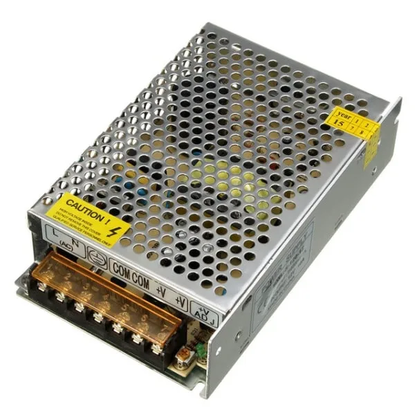
12V 10A SMPS – 120W DC Metal Power Supply
This SMPS contains inductors, capacitors, and diodes working together in a high-frequency switching circuit. Understanding inductors in AC circuits is the key to understanding how SMPS designs achieve high efficiency.
Non-Ideal Inductor Behaviour
A real inductor is not a perfect reactive element. Understanding its parasitic effects is critical for high-frequency design:
Winding Resistance (DCR)
The wire in the coil has resistance. This DCR adds a real impedance in series with the ideal inductive reactance: Z_real = DCR + jXL. For power applications, DCR causes I²R losses and heating. Measure DCR with a multimeter on the Ω setting.
Self-Resonant Frequency (SRF)
Inter-winding capacitance creates a parasitic capacitor in parallel with the inductor. At the self-resonant frequency (SRF), this parasitic capacitance resonates with the inductance, causing the component to behave capacitively above SRF. Always use inductors well below their SRF — at minimum, use at f < SRF/3.
Core Saturation
Ferrite and iron cores saturate when the magnetic flux density exceeds the core’s B_sat. Above saturation current, inductance collapses rapidly. This is critical in power supply inductors — always check that the peak current stays below the inductor’s rated saturation current.
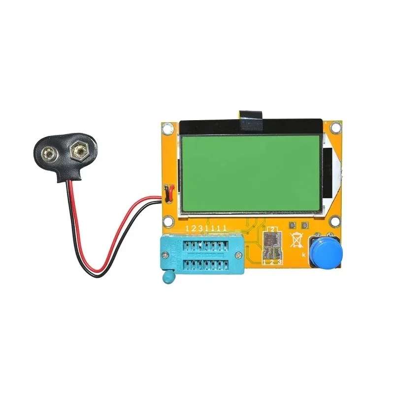
LCR-T4 LCD Graphical Transistor Tester
Measure actual inductance values with the LCR-T4 tester. It also measures capacitance and ESR — essential for verifying hand-wound inductor values before using them in frequency-sensitive AC circuits.
Frequently Asked Questions
Why does an inductor act as a short circuit for DC?
An inductor’s voltage is v = L × di/dt. With steady DC, di/dt = 0, so v = 0 — the inductor produces no opposing voltage. The only resistance to DC current is the physical resistance of the wire (DCR). For an ideal inductor with zero DCR, DC current flows freely — it behaves as a short circuit. This is why inductors are used as DC feeds (chokes) in RF circuits: they allow DC bias to flow while blocking AC signals.
What is the difference between inductive reactance and inductance?
Inductance (L) is a fixed property of the coil measured in Henries (H) — it depends on the coil geometry, number of turns, and core material. Inductive reactance (XL) is the actual opposition to AC current at a specific frequency, measured in ohms: XL = 2πfL. The same inductor presents different reactances at different frequencies. Inductance is constant; reactance varies with frequency.
How do I calculate the cut-off frequency of an RL filter?
For a series RL circuit, the cut-off frequency is f_c = R / (2πL). At this frequency, XL = R and the output is −3 dB. For a high-pass RL filter (output across L), frequencies above f_c pass; below f_c are attenuated. For a low-pass RL filter (output across R), the opposite applies. Example: R = 1kΩ, L = 100mH → f_c = 1000 / (2π × 0.1) = 1592 Hz.
What is Q factor and why is it important for inductors?
The Q factor (quality factor) of an inductor is Q = XL / R_winding = ωL / R, where R_winding is the winding resistance. It represents the ratio of energy stored to energy lost per cycle. A high-Q inductor (Q > 100) has very low losses and behaves close to the ideal. In resonant circuits like LC oscillators and bandpass filters, higher Q gives sharper tuning and lower insertion loss. Ferrite-core inductors typically have Q of 30–100; high-Q air-core inductors for RF can exceed Q = 200.
Can I use an inductor in place of a capacitor in a filter circuit?
Inductors and capacitors are duals — they have complementary behaviour. You can replace a shunt capacitor in a low-pass filter with a series inductor (and vice versa) to achieve the same filtering effect, because a shunt capacitor and a series inductor both attenuate high frequencies. In practice, for low-frequency circuits (audio, power), capacitors are preferred (cheaper, smaller, no saturation). Inductors are preferred at RF frequencies where capacitor ESR becomes problematic and inductor values are small and practical.
Build RL Circuits and Learn by Doing
Find enamelled wire for winding inductors, SMPS modules, and DC power supplies to power your AC circuit experiments. Zbotic ships across India with quality components at great prices.


Add comment