
Float switches are among the simplest, most robust liquid level sensors available. A float switch uses a buoyant float attached to a switch mechanism — as the liquid level rises or falls, the float moves and opens or closes an electrical contact. In combination with an Arduino and relay module, you can build a fully automated tank level control system that fills a tank when it runs low and stops filling when it is full. This tutorial covers float switch wiring fundamentals, different circuit configurations, complete Arduino code, and real-world safety considerations for water pump control.
1. How Float Switches Work
A float switch consists of a sealed switch enclosure containing a reed switch (or micro-switch) and a moveable float — typically a hollow buoyant ball or cylindrical float — attached to or surrounding the switch body. When the liquid level is high, the float rises and triggers the switch. When the level drops, the float falls and releases the switch.
The switch itself is a simple two-terminal device that is either open-circuit or closed-circuit depending on float position. This makes float switches extremely reliable — they have no electronics to fail, no power requirement to operate, and can last tens of millions of switching cycles. They are used in domestic water tanks, industrial sumps, aquariums, and chemical storage vessels worldwide.
Float switches come in two wiring configurations relative to float position:
- Normally Open (NO): The switch opens when the float is down (liquid is low) and closes when the float rises. Used as a “full” indicator.
- Normally Closed (NC): The switch closes when the float is down and opens when the float rises. Used as an “empty” indicator.
Many float switches can be wired either way depending on which pair of terminals you connect to. Always check the datasheet for your specific float switch model.
2. Types of Float Switches
The market offers several float switch form factors, each suited to different applications:
- Vertical float switches: Mount through the side or bottom of a tank. The float travels along a vertical shaft. Common in domestic overhead water tanks. Available in 1m, 2m, or multi-point variants.
- Horizontal float switches: Mount through the side wall. The float pivots on a hinged arm. Good for narrow tanks or sumps where vertical mounting is impractical.
- Cable float switches: The switch housing hangs in the liquid on a cable. As the level changes, the float tilts and the mercury or microswitch inside triggers. The cable length determines the switching point. Common in sewage pits and wells.
- Mini float switches: Small, inexpensive switches used in washing machines, coffee makers, and humidifiers. Often reed-switch based, requiring a magnet in the float.
For an Arduino project controlling a standard domestic water tank, a vertical or horizontal float switch with microswitch contacts (rated 250V AC, 5A or more) is the best choice.
3. Components Required
- Arduino Uno or Nano
- Float switch (250V AC, 5A rated or higher — choose NC type for a “pump on when low” application)
- 5V relay module (single or dual channel, with optocoupler isolation)
- 10kΩ pull-up resistor (if not using Arduino’s internal pull-up)
- Flyback diode (1N4007) — already present on most relay modules
- Water pump (12V DC for testing, or mains-powered for real installations)
- 12V power supply (if using a 12V DC pump for prototyping)
- Jumper wires and breadboard
- Optional: Waterproof enclosure for the Arduino and relay
4. Wiring the Float Switch to Arduino
The float switch is a purely mechanical contact — it does not need power to operate. Wire it as a digital input switch to the Arduino:
| Connection | Details |
|---|---|
| Float switch wire 1 | Arduino digital pin D2 |
| Float switch wire 2 | GND |
| Arduino D2 pin | Enable INPUT_PULLUP in code (or add external 10kΩ pull-up to 5V) |
With pinMode(2, INPUT_PULLUP), the Arduino’s internal 20–50kΩ pull-up resistor holds D2 HIGH when the float switch is open. When the switch closes (float down in a NC switch), D2 is pulled LOW through the switch to GND. This gives a reliable logic signal: HIGH = tank not empty, LOW = tank empty (pump needed).
Keep the float switch wires short and away from mains wiring to avoid induced noise on the signal. For installations where the float switch is far from the Arduino (e.g., the switch is on the tank, the controller is nearby), use shielded cable and connect the shield to GND at the Arduino end only.
5. Wiring the Relay Module for Pump Control
A 5V relay module with optocoupler isolation is the safest way to control a pump from Arduino. The relay module has three groups of pins:
- Control pins: VCC (5V), GND, IN (signal from Arduino)
- Relay contacts: COM (common), NO (normally open), NC (normally closed)
Connect the relay control pins to the Arduino:
- Relay VCC → Arduino 5V
- Relay GND → Arduino GND
- Relay IN → Arduino digital pin D3
For the pump connection (use only for 12V DC pumps in prototype — see safety section for mains):
- Positive terminal of 12V supply → Relay COM
- Relay NO → Positive wire of pump motor
- Negative terminal of supply → Negative wire of pump motor
When Arduino sets D3 LOW (most relay modules are active-LOW), the relay coil energises and COM connects to NO, powering the pump. When D3 is HIGH, COM connects to NC and the pump stops. Active-LOW control is safer because a disconnected or crashed Arduino leaves the output HIGH, keeping the pump off by default — preventing accidental overflow.
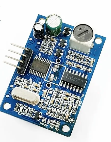
JSN-SR04T Waterproof Ultrasonic Rangefinder
Upgrade from a basic float switch to continuous tank level monitoring — this waterproof ultrasonic sensor measures water level precisely from above the tank without contact.
6. Two-Float System: Fill and Overflow Protection
A single float switch gives you one control point. A two-float system gives you both a low-level trigger (turn pump ON) and a high-level cutoff (turn pump OFF), preventing overflow even if your main logic fails. This is the standard configuration used in professional installations.
- Low-level float switch (D2): Normally Closed. Mounted near the bottom of the tank. When the water level drops below this point, the switch closes (D2 = LOW) → start pump.
- High-level float switch (D3): Normally Open. Mounted near the top of the tank. When the water reaches this level, the switch closes (D3 = HIGH) → stop pump.
The control logic creates a hysteresis band: the pump runs from the low setpoint up to the high setpoint, then rests until the level drops back to the low setpoint again. This prevents the pump from rapidly cycling on and off (“chattering”) which would shorten motor life.
7. Arduino Code: Automatic Tank Filling
// Float Switch Tank Level Control
// Low-level float: D2 (NC, pullup) — LOW when tank is low
// High-level float: D4 (NO, pullup) — LOW when tank is full
// Relay (active-LOW): D3 — LOW turns pump ON

#define LOW_FLOAT_PIN  2
#define HIGH_FLOAT_PIN 4
#define RELAY_PIN      3

#define PUMP_ON  LOW
#define PUMP_OFF HIGH

bool pumpRunning = false;
unsigned long pumpStartTime = 0;
const unsigned long MAX_RUN_TIME = 3600000UL; // 1 hour safety cutoff
const unsigned long DEBOUNCE_MS  = 2000;       // 2-second debounce

void setup() {
  pinMode(LOW_FLOAT_PIN,  INPUT_PULLUP);
  pinMode(HIGH_FLOAT_PIN, INPUT_PULLUP);
  pinMode(RELAY_PIN, OUTPUT);
  digitalWrite(RELAY_PIN, PUMP_OFF); // Ensure pump is OFF on boot
  Serial.begin(9600);
  Serial.println("Tank Level Controller Ready");
}

void startPump() {
  if (!pumpRunning) {
    digitalWrite(RELAY_PIN, PUMP_ON);
    pumpRunning = true;
    pumpStartTime = millis();
    Serial.println("Pump STARTED — tank low");
  }
}

void stopPump(const char* reason) {
  if (pumpRunning) {
    digitalWrite(RELAY_PIN, PUMP_OFF);
    pumpRunning = false;
    Serial.print("Pump STOPPED — ");
    Serial.println(reason);
  }
}

void loop() {
  bool tankLow  = (digitalRead(LOW_FLOAT_PIN)  == LOW); // NC closed = low
  bool tankFull = (digitalRead(HIGH_FLOAT_PIN) == LOW); // NO closed = full

  // Safety: stop pump if it has run for over 1 hour (stuck float / fault)
  if (pumpRunning && (millis() - pumpStartTime > MAX_RUN_TIME)) {
    stopPump("MAX RUN TIME exceeded — check system!");
    while (1); // Halt — require manual reset
  }

  if (tankFull) {
    stopPump("tank full");
  } else if (tankLow && !pumpRunning) {
    delay(DEBOUNCE_MS); // Basic debounce — re-read after 2 seconds
    if (digitalRead(LOW_FLOAT_PIN) == LOW) {
      startPump();
    }
  }

  delay(500); // Check every 500ms
}
Key features of this code: the pump defaults to OFF on startup, there is a 2-second debounce to ignore float bounce, and there is a 1-hour safety cutoff that halts the system if the pump runs continuously (indicating a stuck float or fault). The system requires a manual reset (power cycle) after a safety halt — this prevents unattended overflow.
8. Debouncing and False Trigger Prevention
Float switches can produce multiple rapid transitions as the liquid surface ripples. This is called “switch bounce” and can cause the pump to rapidly start and stop, which is harmful to pump motors and relays. Strategies to prevent this include:
- Software debounce: Read the pin, wait 1–2 seconds, read again. Only act if both readings agree. This is the simple approach used in the code above.
- Hysteresis in code: Once the pump starts, do not stop it until the high-level float triggers. Do not restart until the level drops back to the low float. This prevents micro-cycling from surface ripple near the setpoint.
- Hardware RC filter: A 10kΩ resistor in series with the switch and a 100µF capacitor from the Arduino pin to GND creates a low-pass filter. The capacitor slows the voltage transition, eliminating high-frequency bounce. This is the most reliable hardware solution.
- Timer-based logic: Require the float to remain in position for at least N seconds before triggering an action. Use
millis()for non-blocking timing.
9. Safety Considerations for Mains-Powered Pumps
Most domestic water pumps in India run on 230V AC mains. This requires serious safety precautions that go beyond normal electronics hobbyist practice:
Use a properly rated relay: The relay module must be rated for 230V AC at the pump’s current draw. A 10A, 250V AC relay is the minimum for most single-phase domestic pumps. Many cheap relay modules are rated only for 10A resistive load — inductive motor loads (like pumps) can spike much higher at startup. Use relays with derating for inductive loads, or use a properly sized contactor.
Isolate mains wiring completely: Never run mains and Arduino signal wires in the same cable. Use a relay module with optocoupler isolation so that a mains fault cannot damage your Arduino or cause electric shock on the signal side.
Enclose all mains connections: All 230V terminations must be inside a properly earthed metal or fire-rated plastic enclosure with no exposed live parts. Use terminal blocks, not bare wire connections.
Include an earth leakage circuit breaker (ELCB/RCCB): Protect the pump circuit with a 30mA RCCB. This is legally required in most Indian residential installations and can save lives if the pump motor develops an insulation fault.
Test with low voltage first: Build and test your entire control logic using a 12V DC pump before connecting to mains. Verify all logic is correct before making mains connections.
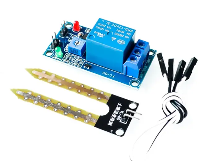
5V/12V Soil Moisture Sensor Relay Module
A great companion module for irrigation projects — combines a moisture sensor and relay in one board, similar to the float switch + relay concept but for soil applications.
10. Advanced: Adding an LCD and Manual Override
Enhance the basic system with a status display and manual control button:
#include <LiquidCrystal_I2C.h>
LiquidCrystal_I2C lcd(0x27, 16, 2);

#define MANUAL_BTN_PIN 5
bool manualMode = false;

// In setup():
lcd.init();
lcd.backlight();
pinMode(MANUAL_BTN_PIN, INPUT_PULLUP);

// In loop():
bool manualBtn = (digitalRead(MANUAL_BTN_PIN) == LOW);
if (manualBtn) {
  manualMode = !manualMode;
  delay(300); // simple debounce
}

lcd.setCursor(0, 0);
lcd.print(pumpRunning ? "PUMP: ON " : "PUMP: OFF");
lcd.setCursor(0, 1);
lcd.print(manualMode ? "Mode:MANUAL" : "Mode:AUTO  ");

if (manualMode) {
  startPump();
} else {
  // normal auto logic here
}
You can also add a buzzer alarm on the safety cutoff condition and an LED indicator for pump status. For remote monitoring, replace the Arduino with an ESP8266/ESP32 and send tank level status to a WhatsApp message or MQTT dashboard.
Frequently Asked Questions
Can I use a float switch directly without Arduino to control a pump?
Yes. For simple on/off control, a float switch with a relay or contactor directly in the pump circuit is a purely electrical solution with no microcontroller. The relay coil is powered through the float switch, energising the relay and running the pump when the float is down. Arduino is needed only if you want automation logic, timers, alarms, or remote monitoring.
What is a stainless steel float switch and when do I need one?
Stainless steel float switches are used in applications involving hot water (above 60°C), corrosive chemicals, food-grade tanks, or high-pressure environments where plastic floats would degrade. For standard domestic water tanks with cold or mildly warm water, plastic polypropylene float switches are perfectly adequate and much cheaper.
My pump keeps cycling on and off rapidly. What should I do?
This is called “hunting” or short-cycling. It happens when a single float switch is used and the tank level sits right at the float’s switching point. Fix it by using two float switches to create a hysteresis band (the pump doesn’t turn off until the tank is truly full). Alternatively, add a 5-minute minimum ON-time timer in software to prevent rapid cycling.
How do I test my float switch before installing it in the tank?
Use a multimeter in continuity mode. Connect the probes to the two switch terminals. Manually move the float to its up and down positions and observe when continuity changes. This confirms whether your switch is NO or NC and that the switch itself is working before you install it in the tank.
Can I use a capacitive or ultrasonic sensor instead of a float switch?
Absolutely. Float switches are binary (on/off), while capacitive or ultrasonic sensors give continuous level readings. An ultrasonic sensor mounted above the tank measures the distance to the water surface, giving you real-time fill percentage. This allows proportional control (slow down the pump as the tank fills) and percentage displays — much more sophisticated than simple float switches.
Build Your Tank Level Controller Today
Shop relay modules, ultrasonic sensors, Arduino boards, and all the components you need to automate your water tank at Zbotic — India’s trusted electronics store.


Add comment