
If you have worked with the ESP32’s built-in ADC (Analog-to-Digital Converter) for any serious measurement project, you have almost certainly hit the frustrating wall of ESP32 ADC accuracy problems — noisy readings, non-linear voltage curves, and results that simply do not match your multimeter. This troubleshooting guide explains exactly why the ESP32 ADC misbehaves, how to fix ESP32 ADC noise, and how to work around the non-linearity to get reliable analog readings for your Indian maker projects.
ESP32 ADC: What You Are Working With
The ESP32 has two ADC units — ADC1 (8 channels on GPIO32–39) and ADC2 (10 channels on GPIO0–27, shared with Wi-Fi). The ADC is 12-bit, meaning it can theoretically resolve 4096 discrete values (0–4095) across its input voltage range. At face value, this sounds impressive, but the actual usable dynamic range is considerably less due to the issues we will cover.
Key ESP32 ADC specifications:
| Parameter | Value |
|---|---|
| Resolution | 12-bit (0–4095) |
| Input range (11dB attenuation) | 0–3.3V (0.15–2.45V usable) |
| Input range (0dB attenuation) | 0–1.0V (more linear) |
| ADC2 with Wi-Fi | Cannot be used (conflicts) |
| Typical noise | ±10–30 LSB (raw) |
Critical rule: Never use ADC2 pins (GPIO0, GPIO2, GPIO4, GPIO12–15, GPIO25–27) when Wi-Fi is active. ADC2 is shared with the Wi-Fi radio hardware and will give garbage readings or cause conflicts. Stick to ADC1 pins (GPIO32–39) for all analog measurements.
Root Causes of ESP32 ADC Noise
Understanding where the noise comes from is the first step to fixing it. ESP32 ADC noise has several sources:
1. Internal Switching Noise
The ESP32 chip is extremely active internally — two CPU cores running at 240 MHz, Wi-Fi radio, Bluetooth stack, and multiple peripherals. All of this switching activity induces noise on the internal power rails, which couples directly into the ADC’s reference voltage and sample-and-hold circuit.
2. Insufficient Decoupling on VDDA
The ESP32’s analog supply pin (VDDA) needs good decoupling capacitors very close to the chip. Many cheap ESP32 dev boards (especially no-name variants sold in India) skip or under-spec these capacitors, resulting in noisy ADC references.
3. Wi-Fi Radio Interference
When Wi-Fi is transmitting, it creates a burst of switching current that rings on the power supply. Even ADC1 readings taken during a Wi-Fi transmission burst will show spikes. This is why sensor reads often show random outliers.
4. High Source Impedance
The ESP32 ADC’s input impedance is low (around 100kΩ in active mode). If your sensor or voltage divider has a high output impedance, the ADC will not fully charge its sample capacitor in time, causing reading errors. Always buffer high-impedance sources with an op-amp or use a low source impedance (below 10kΩ recommended).
5. Floating Inputs
An unconnected ADC pin will read random values as it picks up electromagnetic interference. Always connect unused ADC pins to GND through a resistor, or pull them to a known voltage.
The Non-Linearity Problem Explained
This is the most commonly complained-about ESP32 ADC issue. Even with a perfectly clean, slowly varying DC voltage, the ESP32’s ADC does not produce a linear mapping from voltage to ADC count. The ADC value vs. voltage curve has S-shaped distortion, particularly at the low end (below 0.15V) and the high end (above 2.45V with 11dB attenuation).
A typical measurement with 11dB attenuation on a genuine board:
- 0.00V → ADC reads ~0 (clipped, not linear)
- 0.10V → ADC reads ~50 (should be ~124)
- 1.00V → ADC reads ~1300 (fairly linear zone)
- 2.00V → ADC reads ~2650 (fairly linear zone)
- 2.45V → ADC reads ~3800 (non-linear again)
- 3.30V → ADC reads ~4095 (clipped)
The usable linear range with 11dB attenuation is roughly 0.15V to 2.45V, giving you about 2.3V of actual dynamic range from a 12-bit ADC. Expressed in bits, this is effectively about 10.7 bits of linear resolution — not 12 bits.

LM35 Temperature Sensor
A classic analog temperature sensor — its 10 mV/°C output sits right in the ESP32 ADC’s linear range and is a great test target for ADC accuracy improvements.
Software Fixes: Oversampling and Filtering
Software techniques are your first line of defence against ADC noise and they cost nothing to implement.
Technique 1: Oversampling and Averaging
Take multiple readings quickly and average them. This reduces random noise by a factor of √N, where N is the number of samples. Taking 16 samples effectively gives you about 1 extra bit of resolution (√16 = 4 times noise reduction).
// Average 64 samples for noise reduction
int readADCaveraged(int pin, int samples = 64) {
  long sum = 0;
  for (int i = 0; i < samples; i++) {
    sum += analogRead(pin);
    delayMicroseconds(100); // Small gap between samples
  }
  return sum / samples;
}

void setup() {
  Serial.begin(115200);
  // Use ADC1 pin only!
  analogSetAttenuation(ADC_11db); // 0–3.3V range
  analogSetWidth(12);             // 12-bit resolution
}

void loop() {
  int adcValue = readADCaveraged(34, 64); // GPIO34 = ADC1_CH6
  float voltage = adcValue * (3.3f / 4095.0f);
  Serial.printf("ADC: %d | Voltage: %.3f Vn", adcValue, voltage);
  delay(500);
}
Technique 2: Median Filtering
Median filtering removes spike outliers (like Wi-Fi noise bursts) better than simple averaging. Collect an odd number of samples, sort them, and take the middle value:
int compareInts(const void* a, const void* b) {
  return (*(int*)a - *(int*)b);
}

int readADCmedian(int pin, int samples = 15) {
  int buf[samples];
  for (int i = 0; i < samples; i++) {
    buf[i] = analogRead(pin);
    delayMicroseconds(200);
  }
  qsort(buf, samples, sizeof(int), compareInts);
  return buf[samples / 2]; // Return the middle value
}
Technique 3: Exponential Moving Average (EMA)
For slowly changing signals (temperature, pressure), an exponential moving average smooths readings continuously without buffering:
float emaValue = 0;
float alpha = 0.1f; // 0.05-0.2 is typical (lower = smoother)

void loop() {
  int raw = analogRead(34);
  emaValue = alpha * raw + (1.0f - alpha) * emaValue;
  Serial.println(emaValue);
  delay(50);
}
Hardware Fixes: Decoupling and External References
When software fixes are not enough, hardware improvements make a dramatic difference.
Fix 1: Add Decoupling Capacitors
Place a 100nF ceramic capacitor as close as possible to the ADC input pin (between the pin and GND). For very noisy environments, add a 10µF electrolytic in parallel. This forms a low-pass RC filter with your source impedance, cutting high-frequency noise before it enters the ADC.
Fix 2: Add an RC Low-Pass Filter on the Input
Add a 10kΩ resistor in series with the ADC input, followed by a 100nF capacitor to GND. This RC filter has a cutoff frequency of about 160 Hz, which is more than fast enough for most sensor readings (temperature, pressure, slow potentiometers) while completely eliminating MHz-range switching noise.
Fix 3: Read ADC When Wi-Fi is Quiet
Schedule your ADC reads during Wi-Fi idle windows using the WiFi.setSleep(WIFI_PS_MIN_MODEM) setting, or disable Wi-Fi briefly, take the reading, and reconnect. For applications that need both Wi-Fi and accurate ADC simultaneously, use an external ADC over SPI or I2C.
Fix 4: Use a Voltage Divider Within the Linear Range
If measuring voltages above 2.45V, design your voltage divider so that the maximum expected voltage maps to 2.0V at the ADC input (leaving headroom and staying in the linear zone). Use low-impedance resistors (1kΩ to 10kΩ range) for the divider.
ADC Calibration Using ESP32’s Built-in eFuse Data
Espressif provides an ADC Calibration API in the ESP-IDF framework (also available in Arduino via esp_adc_cal.h). Each ESP32 chip is factory-calibrated with coefficients stored in eFuse that correct for the non-linearity curve. Using this API dramatically improves accuracy:
#include <esp_adc_cal.h>
#include <driver/adc.h>

#define ADC_CHANNEL ADC1_CHANNEL_6 // GPIO34
#define ADC_ATTEN   ADC_ATTEN_DB_11

esp_adc_cal_characteristics_t adc_chars;

void setup() {
  Serial.begin(115200);
  adc1_config_width(ADC_WIDTH_BIT_12);
  adc1_config_channel_atten(ADC_CHANNEL, ADC_ATTEN);

  // Characterise ADC using eFuse coefficients
  esp_adc_cal_characterize(
    ADC_UNIT_1,
    ADC_ATTEN,
    ADC_WIDTH_BIT_12,
    1100, // Default Vref (mV), ignored if eFuse available
    &adc_chars
  );
}

void loop() {
  // Average 64 samples
  uint32_t adc_reading = 0;
  for (int i = 0; i < 64; i++) {
    adc_reading += adc1_get_raw(ADC_CHANNEL);
  }
  adc_reading /= 64;

  // Convert to calibrated millivolts
  uint32_t voltage_mv = esp_adc_cal_raw_to_voltage(adc_reading, &adc_chars);
  Serial.printf("Raw: %d | Voltage: %d mV (%.3f V)n",
                adc_reading, voltage_mv, voltage_mv / 1000.0f);
  delay(500);
}
This calibrated approach typically reduces voltage reading error from ±100–150mV to ±20–30mV, a 5x improvement without any additional hardware.
When to Use an External ADC (ADS1115)
For applications that need truly accurate analog readings — precision weighing, medical sensors, high-resolution audio — no amount of software tricks will make the ESP32’s internal ADC sufficient. In these cases, use an external ADC over I2C or SPI.
The ADS1115 (Texas Instruments) is the most popular choice:
- 16-bit resolution (vs ESP32’s effective 10–11 bits)
- Programmable gain amplifier (±256mV to ±6.144V ranges)
- I2C interface (plug into any ESP32 I2C pins)
- 4 single-ended or 2 differential inputs
- Integrated voltage reference (no noise from ESP32 power rail)
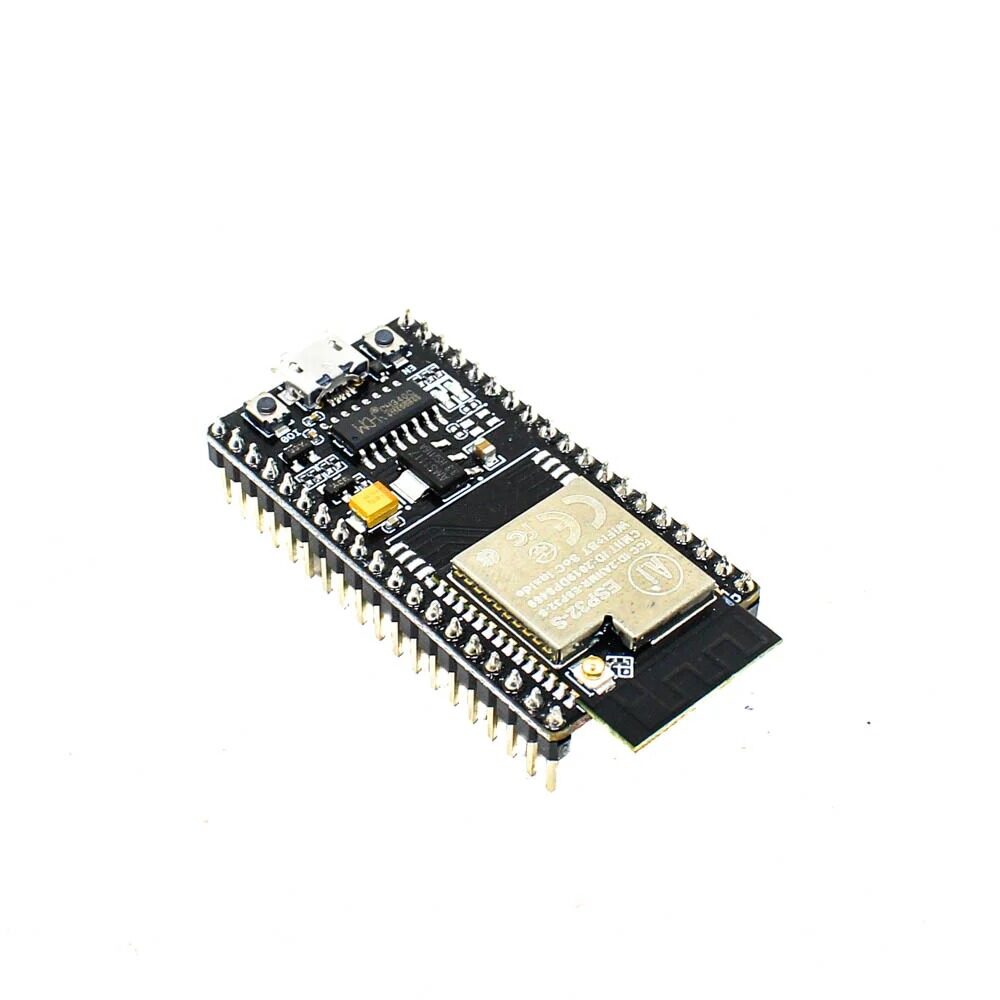
Ai Thinker NodeMCU-32S ESP32 Development Board – IPEX Version
A quality ESP32 board with reliable power regulation — an important factor for better ADC performance. IPEX antenna for strong Wi-Fi to minimise radio interference on ADC.
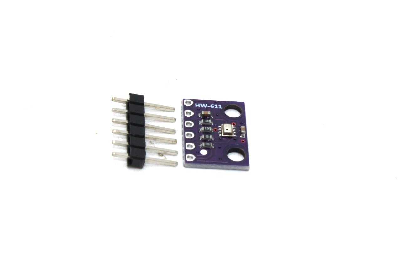
BMP280 Barometric Pressure and Altitude Sensor I2C/SPI Module
An excellent example of a digital I2C sensor that avoids ESP32 ADC limitations entirely — provides precise pressure and temperature without any analog noise issues.
Frequently Asked Questions
Why does my ESP32 ADC reading fluctuate even with no signal connected?
A floating ADC input (nothing connected, or high impedance source) picks up electromagnetic noise from the environment and from the ESP32 itself. Always connect unused ADC pins to GND through a 10kΩ resistor. For connected sensors, use a bypass capacitor (100nF between the ADC pin and GND) to reduce noise pickup.
Can I use ADC2 if I disable Wi-Fi?
Yes. If you stop Wi-Fi (WiFi.disconnect(true); WiFi.mode(WIFI_OFF);), ADC2 becomes available and performs similarly to ADC1. However, as soon as you restart Wi-Fi, ADC2 readings will become unreliable. For applications needing both Wi-Fi and analog readings, use only ADC1 (GPIO32–39).
How much does oversampling actually improve accuracy?
Averaging N samples reduces random noise by √N. Taking 16 samples reduces noise by 4x, which is equivalent to gaining 2 extra bits of effective resolution. Taking 64 samples reduces noise by 8x (3 extra bits). Beyond 256 samples, gains diminish as you start hitting systematic (non-random) error sources that averaging cannot remove.
Is there a good Arduino library for ESP32 ADC calibration?
The esp_adc_cal.h library from Espressif is the standard approach and is included in the ESP32 Arduino board package. There is also the ESP32AnalogRead library on GitHub that wraps the calibration API with a simple getValue() and getMilliVolts() interface. Both are good choices for cleaner calibrated readings.
Why is pin GPIO34/35/36/39 recommended for ADC on ESP32?
GPIO34, 35, 36, and 39 are input-only pins connected to ADC1. Since they are input-only, they have no output driver transistors, which means less internal switching noise and better analog characteristics. They also cannot accidentally be configured as digital outputs, reducing the chance of damaging your sensor circuit.
Get Quality ESP32 Boards and Sensors from Zbotic
Better hardware makes a real difference for ADC accuracy. Shop genuine ESP32 development boards, sensors, and components at Zbotic with fast delivery across India.


Add comment