
Installing a capacitor the wrong way around is one of the most common — and potentially dangerous — mistakes in electronics. An electrolytic capacitor connected with reversed polarity can swell, leak, or in extreme cases explode. This complete guide teaches you everything about electrolytic capacitor polarity: how to identify positive and negative terminals, how to read PCB markings, and how to handle edge cases that confuse even experienced engineers.
Why Electrolytic Capacitor Polarity Matters
Electrolytic capacitors use an electrochemical process to achieve their high capacitance values. An aluminium oxide layer is formed on the positive plate (anode) during manufacture — this oxide layer is the dielectric. This oxide layer forms correctly only when the correct polarity is applied.
When connected backwards:
- The oxide layer dissolves (it was only designed for one direction)
- Electrolytic current flows freely, generating significant heat
- Internal gas pressure builds up rapidly
- The capacitor’s vent (scored top) may rupture to prevent explosion
- In sealed or old capacitors, the body can rupture violently
This is why understanding electrolytic capacitor polarity is not just an academic exercise — it’s a basic safety requirement for anyone working with electronics. Even a modest 100µF 25V capacitor, when reversed and energised, can cause a loud pop and spray caustic electrolyte fluid.
5 Ways to Identify Capacitor Polarity
Manufacturers provide multiple redundant indicators of polarity on electrolytic capacitors. In normal circumstances, you’ll use just one or two of these, but knowing all of them helps when markings are worn or ambiguous:
- Stripe / band marking on the capacitor body
- Lead length difference (longer lead = positive)
- Indentation or marking on the top of the capacitor (less common)
- PCB silkscreen markings on the circuit board
- Multimeter measurement (as a last resort)
The Stripe / Band Marking
The most reliable and visible indicator of polarity on an electrolytic capacitor is the stripe or band that runs along one side of the cylindrical body. This band is almost always printed in white or light grey on the dark body of the capacitor, and it contains a series of minus signs (−−−−) or arrows pointing downward.
Critical rule to remember: The stripe indicates the NEGATIVE terminal.
The lead coming out of the striped side goes to ground (GND or negative). The lead on the opposite side (no stripe) goes to the positive supply or higher voltage.
The stripe typically also contains additional information:
- The capacitance value (e.g., 100µF)
- The voltage rating (e.g., 25V)
- Temperature rating (e.g., 85°C or 105°C)
- Manufacturer code and country of origin
Remember: STRIPE = NEGATIVE = GROUND
Lead Length Method
In new, untrimmed electrolytic capacitors, the two leads are cut to different lengths:
- Longer lead = Positive (+) anode
- Shorter lead = Negative (−) cathode
This is a helpful secondary indicator, but has an important limitation: once leads are trimmed during installation, this method is useless. Always use the stripe marking as your primary reference, especially when working with capacitors that have already been used or soldered onto a board.
The lead length difference is approximately 2-4mm on standard through-hole capacitors. It’s immediately visible when you pick up a new capacitor from a pack.
Reading PCB Silkscreen Symbols
When installing a capacitor on a PCB, the silkscreen (the white markings printed on the board) tells you exactly how to orient the component. Different PCB designers use slightly different conventions, but the most common are:
- A plus (+) symbol next to one pad — insert positive lead here
- A filled/shaded half-circle on the component outline — the shaded half indicates the negative (stripe) side
- A straight line on one side of the circular symbol — indicates the negative terminal (mirrors the stripe on the actual component)
- A D-shaped cutout on one side of the circular pad outline — the flat side of the D indicates the stripe (negative) side
In schematic symbols, the electrolytic capacitor is drawn with a curved plate (negative terminal, cathode) and a straight plate (positive terminal, anode). The + symbol appears on the positive side.
When PCB and Capacitor Markings Conflict
Always trust the PCB silkscreen over the capacitor body if there’s a discrepancy — the PCB is specific to the circuit design. However, if a PCB silkscreen lacks polarity markings (poor design), trust the component body markings and verify with a schematic.
What Happens When Polarity Is Reversed
The severity of reverse-polarity damage depends on the voltage and capacitance:
| Scenario | Typical Outcome | Time to Failure |
|---|---|---|
| Small cap (1µF), low voltage (3.3V), reversed | Slow degradation, leakage increase | Hours to days |
| Medium cap (100µF), 12V, reversed | Gets hot, may pop after minutes | Minutes |
| Large cap (1000µF), 25V+, reversed | Rapid heating, loud pop, electrolyte spray | Seconds |
| Large cap, fully charged, reversed suddenly | Violent rupture possible | Immediate |
Most modern capacitors have a pressure vent — a scored cross or K-shape on the top of the can. When internal pressure builds, this vent ruptures safely before the whole can bursts. It makes a popping sound and releases gas and electrolyte vapour upward. This is designed for safety, but still damages the capacitor and potentially nearby components.
Testing Polarity with a Multimeter
If you have a capacitor with worn or missing markings, you can determine polarity using a digital multimeter in two ways:
Method 1: Diode Test Mode
Set multimeter to diode test (diode symbol). Touch probes to each lead. When red (positive) probe is on the positive lead, the meter shows a reading of ~0.4-0.7V or a finite resistance before climbing. When reversed, the meter shows OL (infinite). Note: This method has limited reliability and works better on lower-capacitance electrolytics.
Method 2: Capacitance and Leakage Test
Using an LCR meter or component tester: measure capacitance in both orientations. The correct polarity will show the rated capacitance value. Reversed polarity will show lower-than-expected capacitance or unusual readings because the oxide layer is not properly formed.
Warning: Never apply excessive voltage to determine polarity by “seeing which way it works” — this risks damaging the capacitor.
Dealing with Unmarked or Faded Capacitors
Old capacitors from salvage, or those stored in humid conditions, may have faded markings. In these cases:
- Check lead length first (only if untrimmed)
- Look for any remaining ink traces on the body with a magnifying glass
- Use an LCR meter to test capacitance in both orientations (takes a few seconds per test)
- If the capacitor is from a known working circuit, photograph it before desoldering so you have a reference
- When in doubt, discard and use a new capacitor — electrolytic caps are inexpensive
Non-Polarized Electrolytic Capacitors
It’s worth knowing that non-polarized electrolytic capacitors exist. These are labeled NP or NP-CAP and are constructed with two anode foils (no cathode foil). They can be connected in either direction and are used in audio crossover circuits and AC applications.
However, non-polarized electrolytics are much less common and typically lower in capacitance than standard polarized types. If a capacitor doesn’t have any polarity marking at all and isn’t ceramic or film type, verify with the original datasheet or circuit schematic — it may be a non-polarized electrolytic intentionally.
Electrolytic vs Ceramic vs Tantalum Polarity
| Type | Polarized? | Polarity Indicator | Risk if Reversed |
|---|---|---|---|
| Aluminum Electrolytic | Yes | Stripe = negative, longer lead = positive | High — can pop or explode |
| Tantalum | Yes | Stripe or + mark = POSITIVE (opposite of electrolytic!) | Very high — may catch fire |
| Ceramic | No | None needed | None |
| Film (polyester) | No | None needed | None |
Critical warning about tantalum capacitors: The polarity marking on tantalum capacitors is the OPPOSITE of aluminum electrolytics. On a tantalum cap, the stripe or band indicates the positive terminal. This is a common source of confusion and errors. Always double-check tantalum polarity markings.
Recommended Products from Zbotic
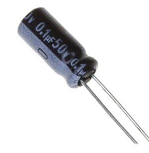
0.1µF 50V Capacitor (Pack of 50)
High-quality 50V-rated decoupling capacitors. Practice identifying polarity markings on freshly packaged components before installing them in your circuits.

0.1µF Ceramic Capacitor (Pack of 50)
Non-polarized ceramic capacitors — use these for decoupling without worrying about polarity. Ideal comparison to learn the difference from electrolytic types.

LCR-T4 12864 LCD Component Tester
Automatically measures and displays capacitance, ESR, and other parameters — and shows which pin is positive when testing electrolytic capacitors. Essential for any workbench.

10CM Female To Female Breadboard Jumper Wires 2.54MM – 40Pcs
When prototyping capacitor-heavy power supply circuits on your breadboard, these jumper wires keep connections clean and organised during polarity testing.
Frequently Asked Questions
Q: What does the stripe on an electrolytic capacitor mean?
A: The stripe on an electrolytic capacitor body indicates the negative (−) terminal. The lead on the striped side connects to ground or the lower voltage point in your circuit. This is the most important marking to remember when working with electrolytic capacitors.
Q: My capacitor has no visible markings — how do I know which lead is positive?
A: Check the lead lengths first — the longer lead is positive on new, untrimmed capacitors. If leads are trimmed, use an LCR meter or component tester to measure capacitance in both orientations; the correct orientation will show the rated value. Alternatively, look for any faint ink traces under magnification, or cross-reference with the circuit schematic.
Q: Can a briefly reversed capacitor still be used after correction?
A: It depends on how long it was reversed and at what voltage. If the reversal was very brief (a second or less) at low voltage, the capacitor may still function, but its oxide layer may be partially damaged leading to increased leakage current over time. For any critical circuit, replace the capacitor after a reversal incident — they are inexpensive and not worth the risk.
Q: Is it safe to use a capacitor above its voltage rating if I install it correctly?
A: No. Exceeding the voltage rating causes breakdown of the oxide dielectric layer, leading to the same failure mode as reversed polarity — heating, gas production, and potential rupture. Always use a capacitor rated for at least 20% above the maximum voltage in your circuit. For a 12V circuit, use 16V or 25V rated caps.
Q: Do I need to worry about polarity in AC circuits?
A: Standard electrolytic capacitors must not be used directly across AC supply lines since AC reverses polarity continuously. Use non-polarized electrolytic (NP type), film capacitors, or ceramic capacitors for AC applications. Some AC motor capacitors are oil-filled types specifically designed for AC use.


Add comment