
Choosing the correct diode type — Zener, Schottky, LED, or TVS — can make the difference between a circuit that works perfectly and one that fails at the worst possible moment. Diodes are everywhere in electronics: in power supplies, signal rectifiers, voltage references, LED indicators, and transient protection circuits. This guide covers every major diode type used in hobbyist and professional electronics, with practical selection advice for Indian makers building Arduino and embedded systems projects.
Table of Contents
- Diode Basics: How a Diode Works
- Rectifier Diodes: 1N4007 and General Purpose
- Schottky Diodes: Low Drop, High Speed
- Zener Diodes: Voltage Regulation and Reference
- Light Emitting Diodes (LED): The Basics
- TVS Diodes: Transient Voltage Suppression
- Other Diode Types: PIN, Tunnel, Varactor
- Diode Comparison Table
- Frequently Asked Questions
Diode Basics: How a Diode Works
A diode is a two-terminal semiconductor device that allows current to flow in one direction (from Anode to Cathode, the forward direction) and blocks it in the reverse direction. The cathode is marked with a silver or white band on through-hole components.
Key diode parameters every hobbyist should know:
- Vf (Forward Voltage): Voltage drop across the diode when conducting. Silicon diodes: ~0.6–0.7V. Schottky: ~0.2–0.4V. LED: 1.8–3.5V depending on colour.
- If (Forward Current): Maximum continuous current the diode can carry.
- Vr (Reverse Voltage / PIV): Maximum reverse voltage before avalanche breakdown occurs.
- Ir (Reverse Leakage Current): Small current that flows in the reverse direction. Schottky diodes have higher leakage than silicon.
- Trr (Reverse Recovery Time): Time for the diode to stop conducting after switching from forward to reverse. Standard silicon diodes: hundreds of nanoseconds. Schottky: near zero.
Rectifier Diodes: 1N4007 and General Purpose
The 1N4007 is the most universally used diode in the world. It is a standard silicon P-N junction diode optimised for rectification — converting AC to DC in power supply circuits.
1N4007 Specifications
- Peak Inverse Voltage (PIV): 1000V
- Average forward current: 1A
- Forward voltage: ~0.7V at 1A
- Reverse recovery time: ~30µs (relatively slow)
The 1N4007 is also used as a flyback/freewheeling diode across relay coils and inductive loads in transistor switch circuits. It is the go-to choice when you need a cheap, robust diode for low-frequency rectification and protection applications.
The 1N400x series (1N4001 to 1N4007) all share the same current rating (1A) but differ in reverse voltage rating: 1N4001 = 50V, 1N4002 = 100V, all the way to 1N4007 = 1000V. For most 12V or 24V circuit protection applications, any of these will work, but the 1N4007 is so cheap and widely available that engineers just use it universally.
For higher currents (3A–6A), use the 1N5400 series or the IN540x series. For bridge rectifiers in power supplies, dedicated bridge rectifier modules (like the W10M, 10A 1000V) are more convenient than four individual diodes.
Schottky Diodes: Low Drop, High Speed
Schottky diodes use a metal-semiconductor junction (instead of P-N silicon) as their core. This gives them two unique advantages over standard silicon diodes: much lower forward voltage drop (~0.2–0.4V vs ~0.7V) and essentially zero reverse recovery time.
Why the Low Forward Voltage Matters
In a 5V to 3.3V power circuit, every millivolt of efficiency counts. A 1N4007 drops 0.7V, wasting 14% of the 5V supply voltage. A Schottky diode like the 1N5819 drops only 0.3V, losing just 6%. In battery-powered Arduino projects, this directly translates to longer battery life.
Common Schottky diodes:
- 1N5819: 1A, 40V — most popular through-hole Schottky for Arduino circuits
- 1N5822: 3A, 40V — for higher-current switching
- SS34 (SMA package): 3A, 40V — common in DC-DC converters
- BAT43, BAT85: Small-signal Schottky, used in RF and high-speed signal detection
- SB540: 5A, 40V — used in flyback converter output stages
Best Use Cases for Schottky Diodes
- Output rectifier in DC-DC buck/boost converters
- Reverse polarity protection (in series with power input)
- OR-ing power supplies (e.g., USB vs. battery selection)
- Freewheeling diode where low voltage drop matters
- High-frequency rectification in SMPS
Schottky Limitations
Schottky diodes have higher reverse leakage current and lower maximum reverse voltage (typically 20–100V) compared to standard silicon diodes. Avoid using them in high-voltage mains rectifier circuits.
Zener Diodes: Voltage Regulation and Reference
A Zener diode is specifically designed to operate in the reverse breakdown region in a controlled manner. When the reverse voltage reaches the Zener voltage (Vz), current flows in the reverse direction while the voltage across the diode remains nearly constant. This makes it useful as a voltage reference and simple shunt regulator.
How a Zener Voltage Regulator Works
A Zener regulator is the simplest possible voltage regulator: connect the Zener diode in reverse (cathode to +V) in series with a current-limiting resistor from the supply. The load connects in parallel with the Zener. As long as the supply voltage and load current stay within design limits, the output voltage equals Vz.
+Vin (e.g. 12V)
   |
  [Rs] (series resistor)
   |
   +---[Load]--- Output = Vz
   |
  [Zener] (cathode to top, anode to GND)
   |
  GND
Rs = (Vin_max − Vz) / (Iz_max + IL_max)
Common Zener diodes available in India: 3.3V, 3.9V, 4.7V, 5.1V, 5.6V, 6.2V, 9.1V, 12V — in 400mW (1N4728–1N4764 series) and 1W (1N4728A–1N4764A) packages.
Zener Diode Applications
- 5V reference for ADC or comparator circuits
- 3.3V level shift protection (with resistor, protect 3.3V GPIO from 5V signal)
- Overvoltage clamping on input lines
- Simple voltage regulator for low-current loads
- Crowbar circuit protection
Zener vs LDO regulator: For any load above 20–30mA, use a proper LDO regulator (like LM7805, LM1117) instead of a Zener shunt regulator. Zener regulators are inefficient under varying load conditions.

LCR-T4 Component Tester — Identifies Diodes Automatically
Plug in any unknown diode and the LCR-T4 displays its type, forward voltage, and pinout. Identifies Zener, Schottky, LEDs, and standard diodes instantly.
Light Emitting Diodes (LED): The Basics
An LED (Light Emitting Diode) is a diode that emits light when forward current flows through it. The wavelength (colour) of light depends on the semiconductor material used: Gallium Phosphide for green/red, Gallium Nitride for blue/white.
LED Forward Voltage by Colour
| Colour | Forward Voltage | Material |
|---|---|---|
| Infrared | 1.2–1.8V | GaAlAs |
| Red | 1.8–2.2V | GaAsP |
| Yellow / Orange | 2.0–2.4V | GaAsP |
| Green | 2.0–3.5V | GaP / InGaN |
| Blue | 3.0–3.5V | InGaN |
| White | 3.0–3.6V | InGaN + phosphor |
Always use a current-limiting resistor with an LED: R = (Vsupply − Vf) / If. For a 5V Arduino and red LED at 20mA: R = (5 − 2) / 0.02 = 150Ω. Use 220Ω as the nearest standard value for a slightly conservative current.
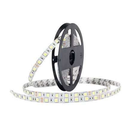
12V Cold White 5050 SMD LED Strip — 5 Meters
High-brightness 5050 SMD LED strip for lighting projects. 12V input, 5-meter roll. Perfect for ambient lighting and illumination projects with Arduino control.
TVS Diodes: Transient Voltage Suppression
Transient Voltage Suppressor (TVS) diodes are specifically engineered to protect circuits against voltage spikes and electrostatic discharge (ESD). When a transient spike exceeds the TVS breakdown voltage, the diode clamps it by absorbing the energy — protecting the sensitive ICs downstream.
Key TVS Diode Parameters
- Standoff Voltage (Vrwm): The maximum normal operating voltage where the TVS remains non-conducting. Choose this above your circuit’s maximum supply voltage.
- Breakdown Voltage (Vbr): The voltage at which the TVS starts conducting. Typically 10% above standoff voltage.
- Clamping Voltage (Vc): The maximum voltage across the TVS during a specified test pulse. This is the protected voltage — your components must survive Vc.
- Peak Pulse Power (Ppk): Maximum energy the TVS can absorb in a single pulse (e.g., 400W, 600W, 1500W, 15kW). Higher is better for harsh environments.
- Response Time: Picoseconds for unidirectional; a few nanoseconds for bidirectional. Much faster than MOVs.
Unidirectional vs Bidirectional TVS
Unidirectional TVS diodes (like 1.5KE12A) clamp positive transients only — suitable for DC power lines. Bidirectional TVS (like 1.5KE12CA) clamp both positive and negative transients — necessary for AC power lines or signal lines that swing both ways (RS-485, CAN bus, analog inputs).
TVS vs MOV vs Zener: What is the Difference?
- TVS diode: Picosecond response, precise clamping, best for PCB-level protection, limited energy absorption.
- MOV (Metal Oxide Varistor): Slower response (~25ns), higher energy absorption, degrades with repeated surges, used for mains-level protection.
- Zener diode: Not designed for transients — limited peak power. Can clamp small signals but will fail on large spikes.
In practice, TVS diodes should be on every data line entering or leaving a PCB (USB, serial, I2C, SPI lines) in products subject to ESD testing. Even in hobby projects, adding a 5V TVS diode on the Arduino’s USB D+ and D- lines can prevent board damage from static discharge.
Other Diode Types: PIN, Tunnel, Varactor
PIN Diode
A PIN diode has an intrinsic (undoped) semiconductor layer between the P and N regions. It behaves as a variable resistor in RF circuits, making it ideal for RF switches, attenuators, and photodetectors. Commonly used in fibre optic receivers and radiation detectors.
Tunnel Diode
Tunnel diodes exploit quantum mechanical tunnelling to conduct current even at very low forward voltages, exhibiting a region of negative resistance. Used in microwave oscillators and extremely high-speed switching applications (GHz range). Rarely seen in hobbyist projects.
Varactor (Varicap) Diode
A varactor diode’s reverse-bias depletion capacitance varies with the applied reverse voltage — effectively making it a voltage-controlled capacitor. Used in voltage-controlled oscillators (VCO), FM radio tuning, and PLL frequency synthesisers.
Diode Comparison Table
| Type | Forward Voltage | Reverse Voltage | Speed | Best Use |
|---|---|---|---|---|
| Rectifier (1N4007) | 0.7V | 1000V | Slow (30µs) | AC rectification, flyback protection |
| Schottky (1N5819) | 0.2–0.4V | 20–100V | Very Fast (<1ns) | SMPS, reverse polarity protection |
| Zener | 0.7V | Vz (controlled) | Slow | Voltage reference, clamping |
| LED | 1.8–3.6V | 5–30V | Fast | Light indication, optocouplers |
| TVS | — | Varies (clamps) | Picoseconds | ESD and transient protection |
| Varactor | — | Varies | Fast | VCO, FM tuning |
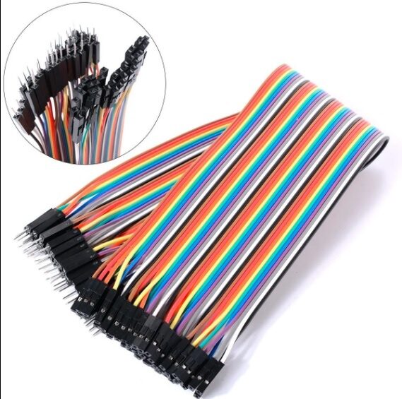
10CM Male To Female Breadboard Jumper Wires — 40Pcs
Essential for prototyping diode circuits on breadboards. 2.54mm pitch, 40 wires per pack — connect Arduino GPIO pins to breadboard components easily.
Choosing the Right Diode for Your Arduino Project
Here is a quick decision guide:
- Protecting transistor from relay back-EMF: 1N4007 (1A, 1000V — robust and cheap)
- Reverse polarity protection on power input: Schottky (1N5819 for 1A loads, SB540 for higher current) — lower voltage drop than 1N4007
- 5V reference for ADC circuits: 5.1V Zener diode with series resistor
- ESD protection on I/O pins: TVS diode (PRTR5V0U2X for USB, or series 5V unidirectional TVS)
- OR-ing two power sources (USB + battery): Two Schottky diodes (one per source) feeding a common output rail
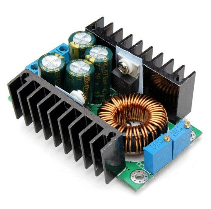
300W 10A DC-DC Step-down Buck Converter
High-efficiency buck converter module that uses Schottky diodes internally for low-loss rectification. Great for powering Arduino and ESP32 projects from higher voltage rails.

DHT11 Temperature and Humidity Sensor Module with LED
Digital sensor module featuring an LED indicator — a practical example of LED integration in real-world sensing circuits. Works with 3.3V and 5V Arduino boards.
Frequently Asked Questions
How do I identify a diode’s cathode vs anode?
On through-hole diodes, the cathode (negative terminal) is always marked with a silver or white band. On SMD diodes, a line or a dot indicates the cathode. In circuit diagrams, the triangle of the diode symbol points in the direction of conventional current flow (anode to cathode), and the vertical line on the tip is the cathode.
Can I use a Zener diode as a regular rectifier diode?
In forward bias, a Zener diode behaves like a regular silicon diode (0.7V drop). You can use it as a rectifier in a pinch, but Zener diodes have lower power ratings and higher cost than standard rectifier diodes. Always use the right type for the application.
What is the difference between a TVS diode and a MOV?
TVS diodes respond in picoseconds, are precise and repeatable, and are ideal for PCB-level ESD protection on signal lines. MOVs (Metal Oxide Varistors) respond in nanoseconds to microseconds, absorb higher energy, degrade with repeated surges, and are better suited for mains-level surge protection (e.g., in power strips). In professional designs, both are often used in cascade.
Why does my LED blow up when I connect it directly to 5V?
An LED has no inherent current limiting — its resistance drops sharply once conducting, resulting in runaway current that instantly burns the LED junction. Always use a series current-limiting resistor. For a standard 5V supply and red LED: use a 220Ω resistor minimum. Never connect an LED directly to a voltage source without a resistor.
What is a Schottky diode used for in DC-DC converters?
In a buck converter, the Schottky diode (the freewheeling diode) provides a path for inductor current when the main switch turns OFF. Its near-zero reverse recovery time prevents shoot-through loss and high-frequency switching noise. Its low forward voltage (~0.3V) reduces conduction loss compared to a standard diode, improving converter efficiency. In synchronous converters, the Schottky is replaced by a MOSFET for even lower losses.
Conclusion: The Right Diode for the Right Job
Diodes are among the most versatile building blocks in electronics. The 1N4007 is your everyday workhorse, the Schottky saves power and handles high-speed switching, the Zener provides stable voltage references, LEDs bring light to your circuits, and TVS diodes silently guard your sensitive ICs against destructive transients. Keep a variety of each type in your component kit, and always check the datasheet before finalising your design. With the right diode in the right place, your circuits will be efficient, reliable, and well-protected.


Add comment