
If you have ever burned out a DC motor or wondered why your robot slows to a crawl when it picks up a load, the answer lives in a simple graph: the torque-speed curve. This characteristic curve is the single most important piece of information on any motor datasheet, yet it’s frequently misunderstood or ignored by beginners.
This guide explains the DC motor torque-speed curve from first principles, walks through every region of the curve, and shows you how to use it to select the right motor and gearbox for your application — whether you’re building a wheeled robot, a conveyor system, or a motorised camera slider.
DC Motor Basics: How It Works
A brushed DC motor converts electrical energy into mechanical rotation using electromagnetic induction. When current flows through the armature winding inside a magnetic field, it experiences a force (the Lorentz force). The commutator — a segmented copper ring — switches current direction as the rotor turns, keeping the force in one rotational direction continuously.
Two equations govern DC motor behaviour:
- Torque: T = Kt × I (torque is proportional to current)
- Back-EMF: Vback = Ke × ω (back-EMF is proportional to speed)
Where Kt is the torque constant, Ke is the back-EMF constant, I is armature current, and ω is angular velocity (rad/s). These two constants are numerically equal when using consistent SI units — a fact that makes motor analysis elegantly self-consistent.
The Torque-Speed Relationship
Applying Kirchhoff’s voltage law around the armature circuit:
V = I × R + Ke × ω
Rearranging for current: I = (V - Ke × ω) / R
Since T = Kt × I, substituting:
T = Kt × (V – Ke × ω) / R
This is a linear equation in T and ω — the torque-speed curve is a straight line (for an ideal DC motor with constant voltage). As speed increases, torque decreases linearly, and as speed decreases (load increases), torque increases linearly. That’s the fundamental insight.
Reading the Torque-Speed Curve
A typical torque-speed curve has torque on the Y-axis (in N·m, kg·cm, or oz·in) and speed on the X-axis (in RPM or rad/s). The line runs from upper-left to lower-right.
The Two Endpoints Define Everything
Only two points are needed to fully describe an ideal DC motor’s torque-speed curve:
- Stall torque (Tstall): The torque at zero speed (motor held completely still). This is the maximum torque the motor can produce. Current is at its maximum here: Istall = V/R.
- No-load speed (ω0): The speed at zero torque (motor running completely free). This is the maximum speed. Back-EMF equals supply voltage: ω0 = V/Ke.
Every operating point the motor can reach lies on the straight line between these two endpoints. The actual torque-speed characteristics of real motors deviate slightly from this ideal line due to magnetic saturation, brush friction, and windage losses, but the linear model is accurate enough for most engineering decisions.
Key Operating Points Explained
Stall Condition
When torque demand exceeds stall torque, the motor shaft does not rotate. All electrical energy converts to heat in the armature resistance. Sustained stall destroys motors quickly — the winding insulation melts. Rule of thumb: never run a DC motor at stall for more than a few seconds unless it is specifically rated for stall (some linear actuators are).
No-Load Condition
With no mechanical load, the motor accelerates until back-EMF nearly equals supply voltage, leaving only enough current to overcome internal friction and windage. Actual no-load current (I0) is small but non-zero. Running at no-load is safe but wasteful if you need torque.
Maximum Power Point
Power (P = T × ω) is maximum at the midpoint of the torque-speed curve — half the stall torque and half the no-load speed. For maximum power transfer you’d operate here, but efficiency is only about 50% at this point. Efficient operation is typically at 70–80% of no-load speed.
Rated Operating Point
The datasheet “rated” or “nominal” operating point is where the motor delivers its rated torque at rated speed while staying within its thermal limit continuously. This is usually at 70–80% of no-load speed. Always design so your load falls in this region.
The Power Curve
Output mechanical power is P = T × ω. Since torque varies linearly with speed on a DC motor, power follows a parabolic curve — zero at both endpoints (stall: ω=0; no-load: T=0) with a peak at the midpoint.
This is why running a large motor lightly loaded is inefficient: you’re on the wrong side of the parabola. Size your motor so the load falls near the peak of the power curve for best energy efficiency. For electric vehicle motors and drone ESCs, this operating point calculation is critical for battery life.
Effect of Gear Ratio
A gearbox multiplies torque by the gear ratio G while dividing speed by the same ratio (ignoring friction losses):
- Output torque: Tout = Tmotor × G × η (η = gearbox efficiency, typically 0.80–0.95)
- Output speed: ωout = ωmotor / G
This effectively scales the torque-speed curve: a 50:1 gearbox stretches the torque axis 50× and compresses the speed axis 50×. The curve is still linear, just with different endpoints.
Choosing Gear Ratio for Your Load
Optimal gear ratio = √(Tload / Tmotor at max power) × some safety factor. In practice:
- Calculate required output torque and speed at your application’s operating point
- Divide required output torque by estimated motor stall torque (× 0.5 for safety)
- That quotient is your minimum gear ratio
- Verify the resulting output speed matches your requirement
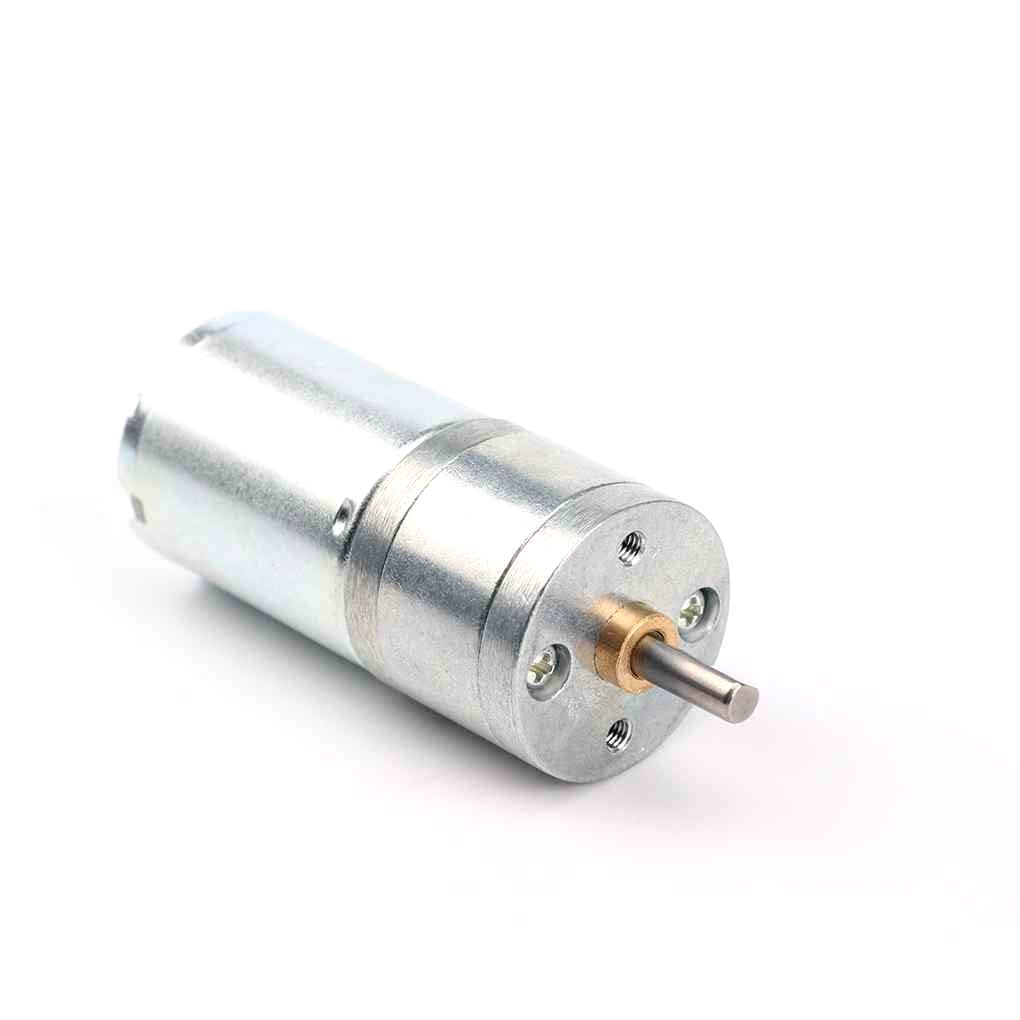
25GA-370 12V 12RPM DC Reducer Gear Motor
Compact 12V gear motor with built-in reduction gearing — ideal when you need high torque at low speed. Study the torque-speed curve to confirm it matches your load requirements.
Effect of Voltage & Temperature
Voltage
Increasing supply voltage scales both endpoints proportionally:
- Stall torque increases (more current at V/R)
- No-load speed increases (higher V means higher back-EMF equilibrium)
- The slope of the torque-speed curve remains the same (slope = -R/KtKe)
This is why running a 6V servo at 7.4V gives noticeably more torque but also risks overheating — the stall current increases proportionally with voltage.
Temperature
As winding temperature rises, copper resistance R increases (~0.4% per °C). Higher R means lower stall current, lower stall torque — the motor gets weaker as it heats up. This is why thermal derating matters: a motor’s torque at 80°C winding temperature may be 15–20% less than its cold specification. Good motor datasheets include torque derating curves vs. ambient temperature.
How to Select a Motor Using the Curve
Follow these steps when selecting a DC motor:
- Define the load: Required torque (Treq) and speed (ωreq) at the output shaft
- Add safety margin: Multiply Treq by 1.5–2.0 for peak loads and friction
- Determine gear ratio: If no motor can directly meet the requirement, compute the needed gear ratio
- Check the operating point: Ensure the load falls in the efficient zone (between 50–80% no-load speed)
- Verify current draw: Calculate I = T / Kt to ensure your power supply and driver can handle it
- Thermal check: Calculate Ploss = I² × R and verify the motor’s thermal resistance allows continuous operation
Worked Example: Wheeled Robot
Target: robot mass 1 kg, wheel radius 30 mm, target speed 0.5 m/s, slope angle 20°.
- Required drive force per wheel (2 wheels): F = mg sin(20°)/2 = 1×9.8×0.342/2 ≈ 1.68 N
- Required torque per wheel: T = F × r = 1.68 × 0.03 = 0.05 N·m = 5.1 kg·cm
- Required shaft speed: ω = v/r = 0.5/0.03 = 16.7 rad/s = 159 RPM
- With 2× safety: Need ~10 kg·cm at ~160 RPM
- Candidate: 25GA-370 12V 12RPM gear motor (stall ~50 kg·cm) with slightly higher RPM variant, or reduce wheel diameter
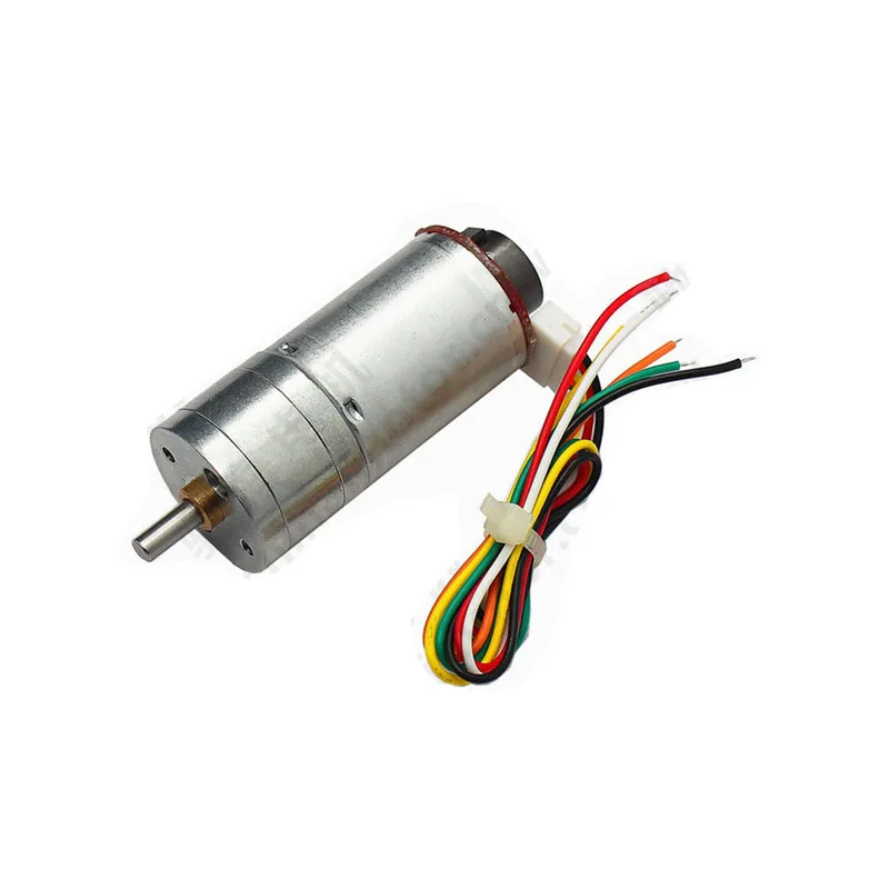
25GA-370 12V 12RPM DC Reducer Gear Motor with Encoder
Same compact gear motor but with built-in quadrature encoder — lets you close the velocity loop and measure actual speed, turning a simple DC motor into a servo-like system.
Gear Motors & Real-World Examples
Gear motors combine a DC motor and a gearbox in a single housing, delivering a practical torque-speed point directly without external gearing. The 25GA-370 series from Zbotic exemplifies this:
- 25GA-370 12V 12RPM: Extreme torque at very low speed — conveyors, slow-moving platforms, valve actuators
- 25GA-370 12V 1360RPM: Moderate torque at moderate speed — wheels, fans, mixer paddles
The naming tells you the gearbox ratio indirectly: a 370-class motor running at ~12,000 RPM no-load into a 1000:1 box yields ~12 RPM. This extreme gear ratio massively multiplies torque at the cost of speed.

25GA-370 12V 1360RPM DC Reducer Gear Motor
Higher-speed variant of the 25GA-370 family — suitable for robot wheels and light conveyor applications where 12 RPM is too slow but high torque is still needed.
Frequently Asked Questions
Why does my DC motor slow down when I add load?
This is exactly what the torque-speed curve predicts. Adding load increases the required torque, which moves the operating point left on the curve (higher torque, lower speed). The motor draws more current to produce more torque, but the increased I×R voltage drop across the armature resistance reduces the effective voltage driving rotation, resulting in lower speed. If load exceeds stall torque, the motor stops entirely.
What is back-EMF and why does it matter?
Back-EMF (back electromotive force) is the voltage generated by the spinning motor windings — it opposes the supply voltage. The faster the motor spins, the higher the back-EMF, and the less current flows. At no-load speed, back-EMF nearly equals supply voltage, leaving almost no current (and thus almost no torque). Understanding back-EMF is essential for designing motor drivers — a sudden motor stop can produce a large voltage spike that destroys MOSFETs if not protected by flyback diodes.
How do I calculate required motor torque for a wheeled robot?
Required torque per drive wheel = (total robot weight × sin(max slope angle) × wheel radius) / (number of drive wheels × drivetrain efficiency). Add 50–100% safety margin for acceleration and friction. Then verify the selected motor’s stall torque exceeds this at your design voltage.
Does voltage affect the slope of the torque-speed curve?
No — voltage shifts both endpoints (stall torque and no-load speed) proportionally, but the slope of the curve (T vs ω) remains the same. The slope depends only on motor resistance R and the motor constants Kt and Ke, not on supply voltage.
What is the difference between continuous and peak torque?
Continuous torque is what the motor can sustain indefinitely without exceeding its thermal limit. Peak torque can be produced briefly (typically 2–5 seconds) during acceleration — it’s limited by current capability (Ipeak = V / R) rather than temperature. Industrial servo drives enforce these limits electronically. DIY motor controllers do not, which is why overloading a motor burns it out.
Zbotic carries DC gear motors, brushless motors, stepper motors, and actuators across the full torque-speed spectrum. Whether you need 12 RPM for a slow conveyor or 2500 RPM for an e-bike, we have it in stock with fast delivery across India. Browse all motors at Zbotic →


Add comment