
Understanding robot arm forward kinematics and DH parameters is the foundation of every serious robotics project. Whether you’re a student building your first 5-DOF robot arm or an engineer designing automated pick-and-place systems, forward kinematics tells you exactly where your end-effector is for any given set of joint angles. In this comprehensive guide, we walk through the Denavit-Hartenberg (DH) convention, matrix transformations, and practical code examples to bring theory into hardware.
What Is Forward Kinematics?
Kinematics is the study of motion without regard to the forces that cause it. In robotics, we split this into two problems:
- Forward Kinematics (FK): Given joint angles (θ₁, θ₂ … θₙ), find the position and orientation of the end-effector in Cartesian space.
- Inverse Kinematics (IK): Given the desired end-effector position, find the joint angles that achieve it.
Forward kinematics is deterministic — there is always exactly one answer. This makes it far simpler to compute and is the starting point for any arm control system. The DH parameter method, proposed by Jacques Denavit and Richard Hartenberg in 1955, gives us a systematic, compact way to write the FK equations for any serial-link manipulator regardless of how many joints or links it has.
The result of the FK calculation is a 4×4 homogeneous transformation matrix that encodes both position (x, y, z) and orientation (roll, pitch, yaw) of the end-effector relative to the base frame.
The Denavit-Hartenberg (DH) Convention Explained
The DH convention attaches a coordinate frame to each link of the robot following a strict set of rules. Once frames are assigned, each consecutive pair of frames is related by exactly four parameters:
| Parameter | Symbol | Description |
|---|---|---|
| Link Length | a | Distance along xᵢ₋₁ from origin of frame i-1 to foot of common normal |
| Link Twist | α | Angle about xᵢ₋₁ from zᵢ₋₁ to zᵢ |
| Link Offset | d | Distance along zᵢ from origin of frame i-1 to foot of common normal |
| Joint Angle | θ | Angle about zᵢ from xᵢ₋₁ to xᵢ (this is the variable for revolute joints) |
For a revolute joint (rotary), θ is the variable and a, α, d are constants defined by the robot’s geometry. For a prismatic joint (linear slide), d is the variable instead.
The four DH transformation steps applied in sequence are:
- Rotate about zᵢ₋₁ by θᵢ
- Translate along zᵢ₋₁ by dᵢ
- Translate along xᵢ by aᵢ
- Rotate about xᵢ by αᵢ
Building the DH Parameters Table
The first practical step in any FK problem is to draw the robot, assign frames, and fill in the DH table. Here is a worked example for a generic 6-DOF industrial-style arm:
| Joint i | aᵢ (mm) | αᵢ (deg) | dᵢ (mm) | θᵢ (variable) |
|---|---|---|---|---|
| 1 | 0 | 90 | d₁ | θ₁ |
| 2 | a₂ | 0 | 0 | θ₂ |
| 3 | a₃ | 90 | 0 | θ₃ |
| 4 | 0 | -90 | d₄ | θ₄ |
| 5 | 0 | 90 | 0 | θ₅ |
| 6 | 0 | 0 | d₆ | θ₆ |
Each row of this table maps directly to one transformation matrix. Your final FK solution is the product of all six matrices: T₀⁶ = T₀¹ · T₁² · T₂³ · T₃⁴ · T₄⁵ · T₅⁶.
Homogeneous Transformation Matrices
Each DH parameter set yields a 4×4 homogeneous transformation matrix of this form:
Tᵢ = | cos(θ)   -sin(θ)cos(α)   sin(θ)sin(α)   a·cos(θ) |
     | sin(θ)    cos(θ)cos(α)  -cos(θ)sin(α)   a·sin(θ) |
     |   0          sin(α)         cos(α)           d     |
     |   0             0               0             1    |
The top-left 3×3 sub-matrix is the rotation matrix R. The rightmost column (first 3 rows) is the position vector p. Together they define a rigid-body transformation in 3D space.
The overall transformation from base to end-effector is the chain product. For a 5-DOF arm:
T_base_to_ee = T01 @ T12 @ T23 @ T34 @ T45
The @ symbol in Python (NumPy) denotes matrix multiplication. The result gives you the position and orientation of the tool centre point (TCP) for any given joint configuration.
Worked Example: 3-DOF Planar Robot Arm
Let’s work through a simple planar 3R arm where all joints are revolute and all links lie in the XY plane (α = 0, d = 0 for all joints). Link lengths: L₁ = 150 mm, L₂ = 120 mm, L₃ = 80 mm.
DH Table:
| i | a (mm) | α | d | θ |
|---|---|---|---|---|
| 1 | 150 | 0 | 0 | θ₁ |
| 2 | 120 | 0 | 0 | θ₂ |
| 3 | 80 | 0 | 0 | θ₃ |
For θ₁=30°, θ₂=45°, θ₃=20°, the end-effector position works out to:
- x = L₁·cos(θ₁) + L₂·cos(θ₁+θ₂) + L₃·cos(θ₁+θ₂+θ₃)
- y = L₁·sin(θ₁) + L₂·sin(θ₁+θ₂) + L₃·sin(θ₁+θ₂+θ₃)
Substituting: x ≈ 129.9 + 0 + (-75.18) ≈ 54.7 mm, y ≈ 75 + 84.85 + 27.36 ≈ 187.2 mm. The end-effector orientation (total angle) = θ₁+θ₂+θ₃ = 95°.
Code Implementation in Python/Arduino
Here is a clean Python implementation using NumPy to compute FK for any n-DOF arm given its DH table and joint angles:
import numpy as np

def dh_transform(a, alpha, d, theta):
    """Return 4x4 DH transformation matrix."""
    ct, st = np.cos(theta), np.sin(theta)
    ca, sa = np.cos(alpha), np.sin(alpha)
    return np.array([
        [ct, -st*ca,  st*sa, a*ct],
        [st,  ct*ca, -ct*sa, a*st],
        [ 0,     sa,     ca,    d],
        [ 0,      0,      0,    1]
    ])

def forward_kinematics(dh_params, joint_angles):
    """dh_params: list of (a, alpha, d) tuples (theta is variable)"""
    T = np.eye(4)
    for (a, alpha, d), theta in zip(dh_params, joint_angles):
        T = T @ dh_transform(a, alpha, d, theta)
    pos = T[:3, 3]           # end-effector position
    rot = T[:3, :3]          # orientation matrix
    return T, pos, rot

# Example: 5-DOF arm (lengths in mm, angles in radians)
dh = [(150, 0, 0), (120, 0, 0), (100, np.pi/2, 0),
      (0, -np.pi/2, 80), (0, np.pi/2, 0)]
angles = np.radians([30, 45, -20, 60, 15])
T, pos, rot = forward_kinematics(dh, angles)
print(f"End-effector position: {pos.round(2)} mm")
On an Arduino or ESP32, the same logic can be implemented using fixed-point math or the FastMatrix library, though floating-point is preferred for accuracy. For real-time control at 50+ Hz, pre-compute trigonometric values and use cached DH constants.

ACEBOTT ESP32 5-DOF Robot Arm Kit Expansion Pack
A fully programmable 5-degree-of-freedom robot arm with ESP32 control — perfect for applying DH parameter calculations on real hardware.

ACEBOTT ESP32 Programmable Robot Arm Kit for Beginners – QD022
Entry-level programmable robot arm kit for students and teens. Great starting platform for learning FK/IK on physical hardware.
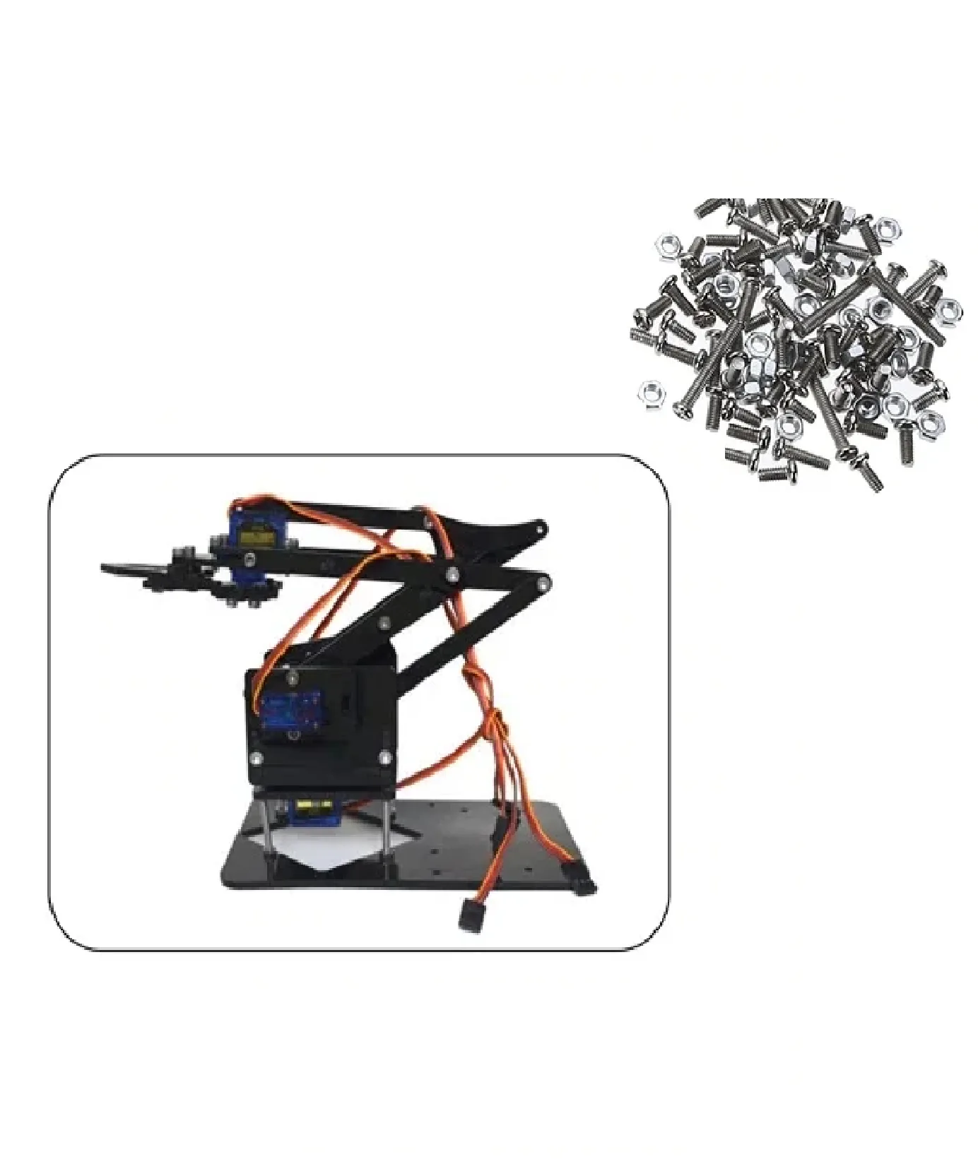
DIY Acrylic Robot Manipulator Mechanical Arm Kit
Bare-bones acrylic manipulator frame (servos and board not included) — ideal for building a custom arm and implementing your own kinematics stack.
Best Robot Arm Kits Available in India
Applying FK theory requires the right hardware. Here’s what to look for when buying a robot arm kit in India:
- Number of DOF: 3-DOF is ideal for learning, 5-6 DOF for industrial-style projects.
- Servo quality: Metal-gear servos (MG996R or above) offer better precision than plastic-gear SG90 for arm control.
- Controller: ESP32 is preferred — it offers Wi-Fi, sufficient processing power for FK math in real time, and PWM channels for multiple servos.
- Structural material: Aluminium extrusion arms are stiffer and better for accuracy. Acrylic is cheaper and fine for learning.
- Software ecosystem: Look for kits with Arduino/MicroPython support so you can implement your own FK code.

Servo Mount Holder Bracket for SG90/MG90 (Pack of 2)
Sturdy mounting brackets for building multi-axis robot arm joints. Compatible with both SG90 and MG90 servos.

TowerPro SG90 180 Degree Rotation Servo Motor
Classic 9g servo motor for lightweight robot arm joints. Excellent for building 3-5 DOF arms where FK concepts are applied.
FAQs on Robot Arm Forward Kinematics
What is the difference between forward and inverse kinematics?
Forward kinematics calculates the end-effector position from known joint angles — it always has one unique answer. Inverse kinematics does the reverse (given a target position, find joint angles) and may have multiple solutions or none at all.
Why use DH parameters instead of other methods?
DH parameters offer a systematic, minimal representation — just four numbers per joint instead of full rotation/translation matrices. This makes it easy to automate FK for any serial-link robot regardless of complexity.
Can I compute FK on an Arduino Uno?
Yes, but the Uno’s limited RAM (2 KB) makes it tight for 6-DOF arms. An Arduino Mega or ESP32 is far more practical. Use pre-computed sine/cosine lookup tables to speed things up.
How accurate is FK in practice?
FK accuracy depends on how precisely you measure the physical DH parameters of your robot. Manufacturing tolerances in 3D-printed or acrylic parts can cause errors of 1-5 mm. Calibration routines (measuring actual positions and fitting DH values) can improve accuracy significantly.
Is there a simulation tool I can use?
Yes — ROS with RViz, Peter Corke’s Robotics Toolbox for Python (free), and MATLAB Robotics Toolbox are the most popular. Peter Corke’s toolbox is especially beginner-friendly and works perfectly with the equations in this guide.
How do I handle the wrist singularity?
Singularities occur when two or more joint axes align, causing the Jacobian to lose rank. For FK specifically, this is not a problem — FK always gives a valid answer. Singularity handling is primarily an inverse kinematics and motion-planning concern.
Start Building Your Robot Arm Today
Now that you understand robot arm forward kinematics and DH parameters, it’s time to put theory into practice. Zbotic.in stocks a range of robot arm kits, servo motors, and ESP32 boards shipped across India. Whether you’re a student, hobbyist, or engineer, we have the right components for your project.


Add comment