
Solderless vs Soldered Connections: Long-Term Reliability Compared
If you’ve spent any time in electronics, you’ve faced the question of solderless vs soldered connections. Should you prototype on a breadboard and leave it there, or take the time to solder everything onto a PCB? What about screw terminals, crimped connectors, and wire-wrap? The answer isn’t always obvious — it depends on the application, the environment, the current levels, and how long the circuit needs to last. This guide digs into the real-world reliability differences between solderless and soldered connections, with practical guidance for Indian makers, students, and professional engineers.
Types of Electrical Connections
Before comparing reliability, it helps to understand the full landscape of connection types used in electronics:
Solderless connections:
- Breadboard (solderless breadboard): Spring-clip contacts that grip component leads and jumper wires. The most common prototyping method.
- Screw terminals and terminal blocks: A screw clamps a wire against a metal contact. Used in power electronics, industrial control panels, and home wiring.
- Crimp connections: A metal ferrule or connector is mechanically deformed to grip a wire. Used extensively in automotive, aerospace, and consumer electronics.
- Wire-wrap: Thin wire is tightly wound around a square post under tension. Used in telecom and high-density digital prototyping.
- Press-fit (compliant pin): A metal pin is pressed into a plated through-hole in the PCB, deforming slightly to create a gas-tight mechanical connection.
- IDC (Insulation Displacement Connector): A sharp metal contact slices through wire insulation to make contact. Used in ribbon cables and phone wiring.
Soldered connections:
- Through-hole solder joint: Component lead inserted through PCB hole and soldered with tin-lead or lead-free solder.
- Surface-mount solder joint (SMT): Component pad soldered to PCB land with paste and reflow oven or hot air.
- Point-to-point soldering: Direct wire-to-wire or component-to-component soldering without a PCB. Used in vintage radio/audio equipment.
- Soldered wire terminations: Wires tinned with solder before insertion into screw terminals or connectors.
Solderless Connections: Advantages and Disadvantages
Breadboard Connections:
The solderless breadboard is the workhorse of electronics education and rapid prototyping in India. Its spring-clip contacts grip 0.6mm (22 AWG) and smaller component leads, making component insertion and removal quick and effortless.
Advantages of breadboard connections:
- Zero tools needed — no soldering iron, no flux, no skill barrier
- Fully reversible — rearrange circuits in seconds
- Components are reusable — no desoldering damage
- Fast prototyping — test a circuit design in minutes
- Safe for beginners — no burns or toxic solder fumes
- Cost-effective for iterative design
Disadvantages of breadboard connections:
- Contact resistance: Breadboard spring clips have 0.1–2 Ω of contact resistance per insertion point — significant for sensitive analogue or high-current circuits
- Stray capacitance: Adjacent rows share capacitive coupling (approximately 1–3 pF) — problematic for RF circuits above ~1 MHz
- Stray inductance: Long jumper wire paths add inductance — causes ringing in fast digital circuits
- Vibration sensitivity: Component leads can work loose under vibration — breadboard circuits should never go into moving equipment
- High-current limitation: Most breadboards are rated for 1–5 A per bus rail — unsuitable for motor drivers or power supplies above a few amperes
- Long-term oxidation: The spring clips oxidise over time (especially in India’s humid coastal environments), increasing contact resistance progressively
- No weatherproofing: A single drop of water can short multiple nodes simultaneously

10CM Male To Female Breadboard Jumper Wires 2.54MM – 40Pcs
Quality jumper wires with firm contacts reduce the main reliability problem of solderless connections. These 10cm M-F wires are ideal for breadboard prototyping and module connections.
Soldered Connections: Advantages and Disadvantages
Advantages of soldered connections:
- Extremely low contact resistance: A good solder joint has contact resistance below 0.01 Ω — effectively negligible in almost all circuits
- Excellent vibration resistance: The solder alloy mechanically bonds the component to the pad, maintaining electrical contact even in harsh vibration environments (automotive, aerospace, industrial)
- Long-term stability: A properly made through-hole solder joint can remain reliable for 20–50 years without any increase in resistance
- High current capacity: Limited only by PCB trace width and component ratings — easily handles tens or hundreds of amperes in power electronics
- Sealed against moisture: The solder alloy itself, combined with PCB conformal coating, can provide good moisture resistance
- RF/microwave capable: Solder joints introduce negligible parasitic capacitance and inductance compared to breadboard contacts
Disadvantages of soldered connections:
- Irreversible (sort of): Desoldering requires skill, tools, and time — components can be damaged by excessive heat during rework
- Skill-dependent quality: A cold solder joint (caused by insufficient heat, contaminated surfaces, or moving the joint before it solidifies) can be worse than no connection at all — intermittent, high-resistance, and invisible to visual inspection
- Thermal stress: Repeated thermal cycling (especially with lead-free solders) can cause solder joint fatigue and cracking over long periods
- Time-consuming: Soldering a complex PCB takes hours; a breadboard prototype takes minutes
- Health considerations: Solder fumes (especially rosin flux fumes) are respiratory irritants — always solder in well-ventilated areas or use fume extractors

0.1MM Copper Soldering Solder PPA Enamelled Repair Reel Wire
Fine 0.1mm enamelled copper wire for detail soldering and repair work. Ideal for point-to-point wiring where you need precision connections in tight spaces.
Long-Term Reliability: The Data
Industry studies and field experience consistently show the reliability ranking of connection types (from most to least reliable in long-term static applications):
- Crimp connections (properly made): Military and aerospace specifications rate high-quality crimp connections as equal to or better than soldering for long-term reliability. A properly crimped connection is gas-tight and immune to flux contamination or cold-joint failure.
- Reflow-soldered SMT joints: Machine-made SMT solder joints with controlled paste volumes and thermal profiles are highly consistent and very reliable.
- Hand-soldered through-hole joints (skilled operator): A skilled technician’s hand solder joint is very reliable but subject to operator variability.
- Wire-wrap: Gas-tight wrapping under tension is excellent for long-term reliability in digital logic — used in telecom switching systems for decades.
- Screw terminal connections: Good for moderate-vibration environments; requires periodic re-tightening in high-vibration applications as thermal cycling can loosen the screw over time.
- Hand-soldered through-hole joints (unskilled operator): Cold joints, insufficient wetting, or disturbed joints during solidification cause intermittent failures.
- Breadboard (solderless) connections: Lowest long-term reliability due to contact oxidation, vibration sensitivity, and variable contact pressure.
In Indian conditions specifically, humidity is a significant factor. Coastal cities like Mumbai, Chennai, and Kolkata have high relative humidity year-round. Breadboard spring clips exposed to humid air oxidise progressively — a breadboard that worked fine 6 months ago may develop intermittent connections without any visible change. PCBs with conformal coating or basic lacquer spray can last decades in the same environment.
How Environment Affects Reliability
The environment where a circuit operates has a massive influence on which connection type is appropriate:
High humidity (coastal India — Mumbai, Chennai, Goa):
Avoid unprotected breadboard connections for anything meant to last more than a few months. Oxidation on spring clips increases contact resistance and creates intermittent behaviour. Soldered circuits should receive at least one coat of acrylic conformal spray.
High temperature (industrial environments, outdoors in summer):
Lead-free solder (SAC305 alloy — 96.5% Sn, 3% Ag, 0.5% Cu) handles higher temperatures better than tin-lead, but is more susceptible to fatigue cracking under thermal cycling. Screw terminals with appropriate locking compound perform better in high-vibration + high-temperature environments.
Vibration (robotics, vehicles, drones):
Breadboard circuits absolutely must not be used in any vibrating application — the contacts will intermittently open within hours. Crimp connectors with proper strain relief, or soldered joints with mechanical stress relief (a small loop in the wire before the solder joint), are the correct approach.
Low-current analogue signals:
For signals below 1mA (sensor outputs, audio, RF), even tiny contact resistance creates noise and signal loss. Only soldered joints or high-quality crimp connections should be used in low-level signal paths. Breadboard connections can introduce millivolts of noise through contact resistance variation.
When to Use Solderless vs Soldered
| Situation | Recommended Connection | Reason |
|---|---|---|
| Learning / first circuit | Breadboard | No soldering skill needed; fully reversible |
| Rapid prototype / proof of concept | Breadboard | Fastest iteration; no commitment |
| Final product / semi-permanent build | Soldered (through-hole or SMT) | Long-term reliability, low resistance |
| High-current power connections (>5A) | Crimp or screw terminal | Better current carrying, less heat buildup |
| RF / high-frequency circuits | Soldered (PCB) | Minimal stray capacitance and inductance |
| Field-replaceable connections | Screw terminals or quality connectors | Can disconnect/reconnect without tools |
| Vibrating / mobile equipment | Crimped or soldered with strain relief | Breadboard fails; solder joints need relief |
What Makes a Reliable Solder Joint
Since soldering is clearly superior for long-term reliability, the question becomes: how do you ensure your solder joints are actually reliable? Here are the key factors:
Surface preparation: Both the component lead and the PCB pad must be clean and free of oxidation before soldering. Flux removes oxides during soldering; but if components have been sitting in storage for years, pre-cleaning with isopropyl alcohol helps.
Correct temperature: A good soldering iron tip temperature for standard tin-lead solder (Sn63/Pb37) is 320–360°C. For lead-free solder (SAC305), use 360–400°C. Too cold = cold joint (dull, grainy, high-resistance). Too hot = burns flux before it can work, lifts PCB pads, and damages components.
Thermal mass considerations: Heat the joint, not the solder. Touch the iron to both the component lead and the PCB pad simultaneously, wait 1–2 seconds for them to reach soldering temperature, then feed solder into the joint (not onto the iron). This ensures the solder flows into the joint rather than balling up on the iron tip.
Signs of a good solder joint: Shiny, smooth, concave fillet that wets to both the component lead and the PCB pad. Not too much solder (ball-shaped = too much). Not too little (visible gaps between solder and pad).
Signs of a cold joint: Dull, grey, granular appearance. May look like it’s attached but has microscopically poor contact. Cold joints often cause intermittent failures that are very difficult to diagnose.
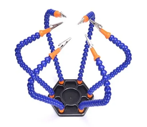
6 Flexible Arms Soldering Station With Swiveling Alligator Clip
A proper soldering station with flexible helping hands dramatically improves joint quality. Hold components in place while both hands control the iron and solder wire for consistent, reliable joints.

BAKON Soldering Iron Tip 900M-T-I
A clean, well-tinned soldering iron tip is the single biggest factor in joint quality. This BAKON chisel tip gives excellent thermal contact for through-hole component soldering.
Frequently Asked Questions
Q1: Is it okay to permanently use a breadboard circuit?
Technically yes for very low-stakes, indoor, stationary applications — a breadboard in a controlled lab environment can work reliably for months or years. But for anything that needs to be reliable — in a product, in a vehicle, outdoors, in humid conditions, or in a circuit that can cause problems if it fails — solder it properly. The effort invested in soldering pays off immediately in reliability and peace of mind.
Q2: Can I solder wires into screw terminals for better reliability?
Pre-tinning wires (applying a thin coat of solder to the bare copper strands before inserting into a screw terminal) is actually a controversial practice. While it prevents individual strands from fraying, the solder can creep under mechanical load from the screw, reducing clamp force over time. For solid core wire in screw terminals, no tinning is needed. For stranded wire, use a proper wire end ferrule (bootlace ferrule) instead — crimp it onto the stripped wire end before inserting into the screw terminal for the best of both worlds.
Q3: How long do breadboard connections last?
In a clean, low-humidity indoor environment, a quality solderless breadboard can maintain reliable connections for 1–3 years of regular use before the spring clips begin to show elevated contact resistance. In coastal or humid Indian environments, this can drop to 6–12 months. The jumper wires often fail before the breadboard itself — the spring contacts inside female jumper wire connectors fatigue with repeated insertions.
Q4: What is the contact resistance of a breadboard connection?
A fresh, clean breadboard contact has approximately 0.1–0.5 Ω of contact resistance. After 6–12 months in service, this can rise to 2–10 Ω, which is significant enough to cause voltage drops in low-voltage circuits (e.g., 3.3V logic) and measurement errors in analogue circuits. For comparison, a good solder joint is typically below 0.01 Ω.
Q5: Are solderless connections ever preferred over soldering in professional electronics?
Yes — in specific applications. Professional-grade crimp connectors (AMP/TE, Molex, JST series) used in automotive and aerospace are preferred over soldering because they create gas-tight, vibration-resistant joints without the risk of cold solder joints, solder cracks, or heat damage to wiring insulation. Wire-wrap is still used in custom telecom equipment for its excellent long-term reliability and repairability. And in power electronics, bolted bus-bar connections handle hundreds of amperes where soldering would be impractical.
Get Soldering and Prototyping Supplies from Zbotic
Whether you’re prototyping on breadboard or ready to solder your final circuit, Zbotic has everything you need — jumper wires, prototype PCBs, soldering supplies, and components. Fast delivery across India.


Add comment