
Introduction
Whether you are cleaning up the output of a power supply or routing audio signals to the right speaker driver, LC filter design is one of the most powerful tools in an electronics engineer’s toolkit. LC filters — built with inductors (L) and capacitors (C) — offer sharp roll-off, low loss, and no signal amplification requirement, making them ideal for both power and signal applications. In this tutorial, we will walk through the fundamentals of LC filter design for low-pass and high-pass configurations, complete with cutoff frequency formulas, quality factor (Q) analysis, and step-by-step design examples relevant to hobbyists and students in India.
Table of Contents
- What is an LC Filter?
- LC Low-Pass Filter: Design and Calculations
- LC High-Pass Filter: Design and Calculations
- Resonance, Quality Factor, and Bandwidth
- LC Filter vs RC Filter: When to Use Which
- LC Filters in Power Supply Design
- Practical Design Tips for Indian Makers
- Frequently Asked Questions
What is an LC Filter?
An LC filter is a passive filter network that uses an inductor (L) and a capacitor (C) to select or reject specific frequency ranges. Unlike resistor-capacitor (RC) filters, LC filters do not dissipate energy — they store and release it between the inductor and capacitor. This makes them highly efficient for high-frequency and high-power applications where signal or power loss in a resistor would be unacceptable.
The inductor opposes rapid changes in current (its impedance increases with frequency: ZL = 2πfL), while the capacitor opposes rapid changes in voltage (its impedance decreases with frequency: ZC = 1/(2πfC)). By combining these two reactive elements in different configurations, you can create filters that pass low frequencies while blocking high ones (low-pass), or pass high frequencies while blocking low ones (high-pass).
LC filters are also the basis of bandpass and band-stop (notch) filters when arranged in series or parallel resonant circuits — but in this tutorial we focus on the fundamental low-pass and high-pass designs.
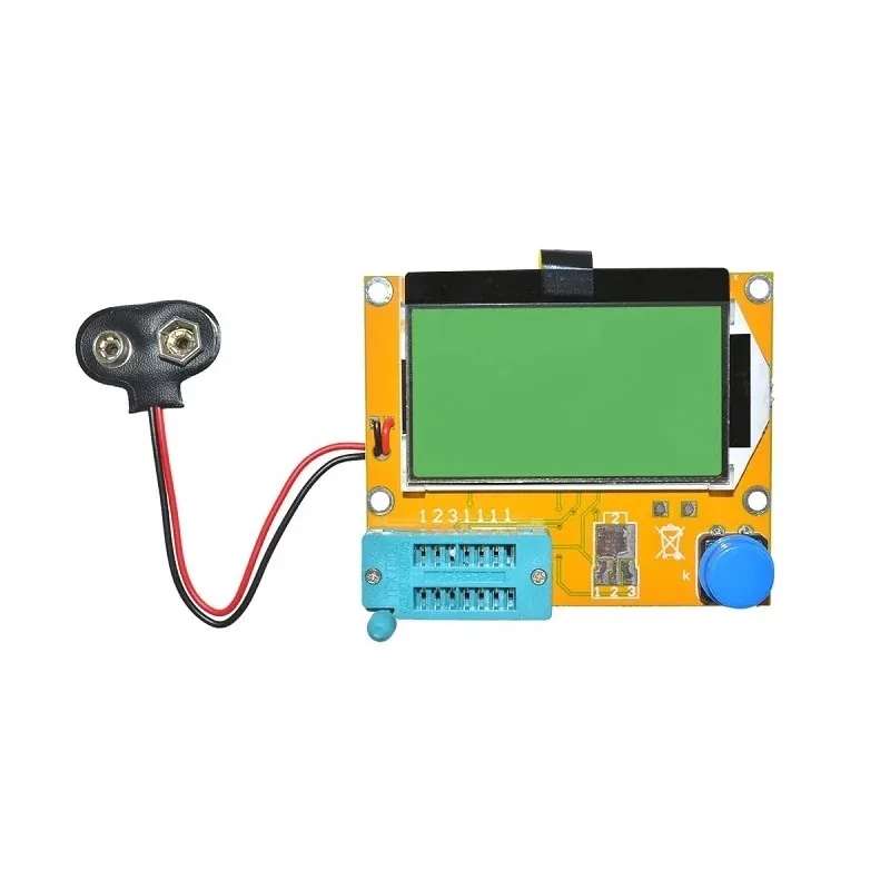
LCR-T4 Transistor & Component Tester
Measure inductance, capacitance, and resistance with ease. Verify your LC filter components before assembly — essential for accurate filter designs.
LC Low-Pass Filter: Design and Calculations
An LC low-pass filter allows signals below the cutoff frequency to pass through while attenuating signals above it. The standard L-section LC low-pass filter has the inductor in series with the signal path and the capacitor shunted to ground.
Circuit Topology
For an L-section low-pass LC filter:
- Input → Inductor (L) in series → Output
- Capacitor (C) connected from the junction between L and the output, to ground
At low frequencies: the inductor has low impedance (passes current freely), and the capacitor has high impedance (draws little current to ground) — so the signal passes through largely unattenuated.
At high frequencies: the inductor’s impedance rises, blocking current. Simultaneously, the capacitor’s impedance falls, shunting signals to ground. The combination attenuates high-frequency signals sharply.
Cutoff Frequency Formula
fc = 1 / (2π × √(L × C))
This is the resonant frequency of the LC circuit — where the impedances of L and C are equal. Below fc, signals pass; above fc, signals are attenuated at −40 dB/decade (much steeper than an RC filter’s −20 dB/decade).
Design Example: 10 kHz LC Low-Pass Filter
Suppose you want a low-pass filter with a cutoff at 10 kHz for an audio crossover application. Choose L = 1 mH:
C = 1 / (4π² × fc² × L)
C = 1 / (4 × 9.87 × 108 × 0.001)
C = 1 / (3.95 × 10⁶)
C ≈ 253 nF → use 220 nF or 270 nF (nearest standard value)
T-Section and π-Section Low-Pass Filters
For better attenuation and impedance matching, use T-section (L-C-L) or π-section (C-L-C) designs. These are common in RF engineering and power supply EMI filters. The T-section has two inductors (L/2 each) with a capacitor to ground in the middle. The π-section has two capacitors (C/2 each) to ground with an inductor in series.
LC High-Pass Filter: Design and Calculations
An LC high-pass filter allows signals above the cutoff frequency to pass through while attenuating signals below it. The components are swapped compared to the low-pass: the capacitor goes in series and the inductor is shunted to ground.
Circuit Topology
- Input → Capacitor (C) in series → Output
- Inductor (L) connected from the junction between C and the output, to ground
At high frequencies: the capacitor has low impedance (passes signals freely), and the inductor has high impedance (does not shunt much to ground) — so the signal passes through.
At low frequencies: the capacitor blocks DC and low-frequency signals. The inductor has low impedance and shunts any low-frequency signal to ground. The result is clean high-frequency passage with sharp low-frequency rolloff at −40 dB/decade.
Cutoff Frequency Formula
fc = 1 / (2π × √(L × C))
The same formula as the low-pass filter — the cutoff frequency depends only on the product L×C, regardless of which configuration you use.
Design Example: 1 kHz LC High-Pass Filter
Design a high-pass filter with cutoff at 1 kHz. Choose C = 100 nF:
L = 1 / (4π² × fc² × C)
L = 1 / (4 × 9.87 × 106 × 10-7)
L = 1 / (3.95 × 10⁻¹)
L ≈ 253 mH → use 220 mH or 270 mH
At 1 kHz, a 253 mH inductor is quite large physically. This is why RC high-pass filters are more common at audio frequencies, while LC high-pass filters are preferred at RF frequencies where smaller inductors suffice.

0.1µF Ceramic Capacitor – Pack of 50
High-quality 104 ceramic capacitors for LC and RC filter prototyping. Their stable capacitance over temperature makes them ideal for filter circuits requiring accuracy.
Resonance, Quality Factor, and Bandwidth
At the resonant frequency (fc), the impedances of the inductor and capacitor are equal in magnitude but opposite in phase. They cancel each other out. In a series LC circuit (series resonance), the impedance drops to near zero at resonance — it acts like a short circuit for that frequency. In a parallel LC circuit (parallel resonance or tank circuit), the impedance rises to a very high value at resonance — it acts like an open circuit.
Quality Factor (Q)
The quality factor Q describes how “sharp” the resonance is. A high-Q filter has a narrow, peaked response; a low-Q filter has a broad, gentle response. Q is defined as:
Q = (1/R) × √(L/C)
Where R is the parasitic resistance of the inductor winding (ESR — Equivalent Series Resistance). A good quality inductor has low ESR and thus high Q. For general filtering, Q values of 5–20 are common. For RF tank circuits and crystal oscillators, Q values of 50–500 or higher are desired.
Bandwidth
Bandwidth (BW) = fc / Q
A filter with fc = 100 kHz and Q = 10 has a bandwidth of 10 kHz around resonance. This concept is used in bandpass filter design to select a specific channel or frequency range.
LC Filter vs RC Filter: When to Use Which
| Parameter | LC Filter | RC Filter |
|---|---|---|
| Roll-off rate | −40 dB/decade | −20 dB/decade |
| Power dissipation | Very low (reactive components) | Higher (resistor dissipates power) |
| Best frequency range | RF, high-power, audio crossovers | Audio, low-frequency signals |
| Component size | Larger (inductors are bulky at low freq.) | Very compact |
| Cost | Higher (inductors are expensive) | Lower (resistors are cheap) |
| Signal loss | Minimal in pass band | Some insertion loss |
| Impedance matching | Yes (important in RF) | No |
LC Filters in Power Supply Design
One of the most important practical applications of LC filters for Indian hobbyists is in DC power supply filtering. After a bridge rectifier, the pulsating DC has a 100 Hz ripple (at India’s 50 Hz mains frequency). An LC filter (also called an L-C choke filter) can dramatically reduce this ripple.
Choke-Input Filter
In a choke-input LC filter, the inductor (choke) is placed first, followed by the capacitor. The inductor’s high impedance at 100 Hz prevents rapid current surges, and the capacitor smooths the remaining ripple. This configuration gives better voltage regulation than a capacitor-input filter (lower output voltage under no load, but more stable under varying loads). It is used in high-quality linear power supplies and vintage valve (tube) amplifier power supplies.
EMI Filter
LC filters on the mains input of switching power supplies (SMPS) prevent high-frequency switching noise from polluting the mains and from entering sensitive circuits. These EMI filters are mandatory in CE/BIS-certified equipment and use X/Y capacitors and common-mode/differential-mode inductors. If you are designing a product for the Indian market (BIS RoHS compliance), ensure your SMPS design includes a proper EMI filter stage.
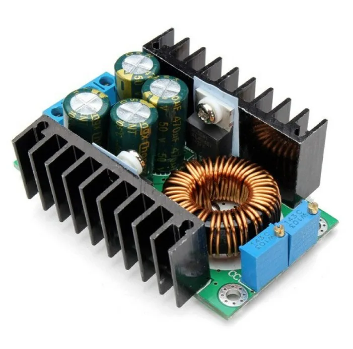
300W 10A DC-DC Step-Down Buck Converter
A buck converter uses an LC filter internally (inductor + output capacitor) to convert DC efficiently. Great for learning how LC filters work in a real switching regulator context.
Practical Design Tips for Indian Makers
- Inductor DCR matters: The DC resistance (DCR) of your inductor causes voltage drop under DC load (relevant in power supply LC filters). Choose inductors with low DCR — preferably under 0.5Ω for power applications.
- Capacitor ESR matters too: Electrolytic capacitors have significant ESR (Equivalent Series Resistance) which limits their effectiveness at high frequencies. For RF filter capacitors, use ceramic or film capacitors with very low ESR.
- Capacitor tolerance: Standard electrolytic capacitors have ±20% tolerance — this shifts your cutoff frequency. For precision filters, use film capacitors (±5% or better) or measure and sort components with an LCR meter.
- Ferrite beads: For very high frequency (MHz range) noise filtering on power supply rails, a ferrite bead acts as a frequency-dependent resistor. Combined with a bypass capacitor, a ferrite bead + capacitor forms a simple but effective high-frequency LC filter for PCB design.
- Core saturation: If your inductor carries too much DC current, its core may saturate, drastically reducing inductance. Always choose an inductor with a saturation current rating higher than your maximum operating current.
- Shielding: Inductors radiate and pick up electromagnetic interference. In sensitive designs, use shielded inductors or orient inductors at right angles to each other to minimise mutual coupling.

0.1µF 50V Capacitor – Pack of 50
Polyester film capacitors with tight tolerance and low ESR — the ideal choice for LC filter circuits where accuracy and stability matter more than size.
Frequently Asked Questions
Q1: What is the cutoff frequency of an LC filter?
The cutoff frequency (also called the corner frequency or −3dB frequency) is the frequency at which the filter’s output power drops to half of the pass-band value (−3 dB in voltage). For an LC filter it is calculated as fc = 1 / (2π√LC). Below this frequency (for low-pass) or above it (for high-pass), signals pass freely. The transition is much sharper than an RC filter — −40 dB/decade vs −20 dB/decade.
Q2: Why does an LC filter have steeper roll-off than an RC filter?
An RC filter is a first-order filter (one reactive element), giving −20 dB/decade roll-off. An LC filter is a second-order filter (two reactive elements), giving −40 dB/decade roll-off. Each additional reactive stage adds another −20 dB/decade of roll-off. A 3-stage LC ladder (Chebyshev or Butterworth) can achieve −120 dB/decade of roll-off — effectively brick-wall filtering.
Q3: Can I use an LC filter for audio crossover design?
Yes — LC crossover filters are the preferred choice in passive loudspeaker crossovers for driving woofers (low-pass) and tweeters (high-pass). They have very low insertion loss (compared to RC filters), can handle the power levels involved without dissipating heat, and provide the second-order (12 dB/octave) slope needed for proper driver integration. A typical 2-way crossover at 3 kHz with 8Ω speakers uses L ≈ 0.85 mH for the woofer low-pass and C ≈ 11.2 µF for the tweeter high-pass.
Q4: How does an LC filter differ from an LC tank circuit?
Both use an inductor and capacitor, but in different configurations. An LC filter is typically an L-section or ladder network designed to pass or reject frequency bands. An LC tank circuit (parallel resonant circuit) is designed to resonate at one specific frequency — it presents very high impedance at resonance and is used in oscillators and RF amplifier tuning stages. The tank circuit is the basis of the tuned circuits in radios and transmitters.
Q5: What happens if I reverse L and C in an LC low-pass filter?
Swapping the position of L and C converts the low-pass LC filter into a high-pass LC filter. The cutoff frequency remains the same (it depends only on the product L×C), but the frequency response is mirrored — signals below fc are now attenuated, and signals above fc are passed.
Conclusion
LC filter design is a foundational skill that spans power supply engineering, audio electronics, and RF communications. The key formula — fc = 1/(2π√LC) — is simple, but the practical implementation requires understanding Q factor, component parasitics, and topology choices. By mastering LC filters, you can build cleaner power supplies, design audio crossovers, and create noise-free signal paths for your microcontroller and sensor projects.
Zbotic stocks capacitors, resistors, and a wide range of electronic components to help you prototype and build your LC filter designs. Browse our Electronics Components collection and get started today!


Add comment