
When your project needs to switch loads beyond what a BJT transistor can handle — high-power LED strips, large motors, heating elements, or anything above a few amps — a MOSFET as a switch is the right choice. MOSFETs combine voltage-controlled operation (no base current needed), ultra-low on-resistance (milliohms), and fast switching into one efficient package. This tutorial covers the IRF540N N-channel MOSFET in detail: how it works, how to design the gate drive circuit, how to calculate the gate resistor, and how to build practical switching circuits for Arduino and other microcontrollers.
MOSFET Basics: Gate, Drain, Source
MOSFET stands for Metal-Oxide-Semiconductor Field-Effect Transistor. Unlike a BJT (which is current-controlled), a MOSFET is voltage-controlled. The three terminals are:
- Gate (G): The control terminal. Applying voltage here creates or destroys the conductive channel. The gate is insulated from the channel by a thin oxide layer — it draws essentially zero steady-state current (just charging/discharging the gate capacitance during switching).
- Drain (D): Connects to the load (positive supply through the load for N-channel). Current flows in through the drain.
- Source (S): Connects to ground (for N-channel low-side switching). Current flows out through the source.
The key advantage over BJTs: because the gate is insulated, it draws no DC current from the control circuit. An Arduino pin can directly drive a MOSFET gate (through a small resistor) without worrying about current gain or base overdrive calculations — as long as the gate voltage is high enough to fully turn ON the MOSFET.
N-Channel Enhancement Mode Operation
The IRF540N is an N-channel enhancement mode MOSFET. “Enhancement mode” means the MOSFET is normally OFF — no channel exists without a gate voltage. Applying positive voltage between Gate and Source (Vgs) creates the channel and allows current to flow from Drain to Source.
Three Operating Regions
- Cutoff (OFF): Vgs < Vth (threshold voltage). No channel. No drain current. MOSFET is OFF.
- Linear/Triode (fully ON): Vgs > Vth and Vds is small. The channel is fully formed. The MOSFET behaves like a low-value resistor (Rds_on). This is where you want it for switching.
- Saturation (partially ON): Vgs > Vth and Vds is large. Drain current is controlled by Vgs. This is the amplifier region — avoid it for switching (high power dissipation).
For switching, you want to drive the MOSFET as hard into the linear region as possible (high Vgs) to minimise Rds_on and thus power dissipation (P = I² × Rds_on).
IRF540N Key Specifications
| Parameter | Value | Notes |
|---|---|---|
| Max Drain-Source Voltage (Vdss) | 100V | Max supply voltage for the load |
| Max Continuous Drain Current (Id) | 33A | At 25°C with adequate heatsink |
| On-Resistance (Rds_on) | 44mΩ | At Vgs=10V, Id=28A |
| Gate Threshold Voltage (Vth) | 2–4V | Starts to turn ON at this Vgs |
| Gate Voltage for full turn-ON | 10V | Rds_on specified at Vgs=10V |
| Max Gate-Source Voltage (Vgs_max) | ±20V | Do not exceed — gate oxide damage |
| Total Gate Charge (Qg) | 72nC | At Vgs=10V |
| Package | TO-220 | Can mount heatsink to tab |
Important: The IRF540N requires Vgs = 10V for its lowest Rds_on. At Vgs = 5V (Arduino logic level), it partially turns ON but with higher Rds_on (around 150–250mΩ, varying by specimen). For loads above 2–3A, this causes significant heating. For 5V logic control of high-current loads, use a logic-level MOSFET (see below) or add a gate drive circuit to boost the gate voltage.
Gate Drive Circuit Design
The gate of a MOSFET is purely capacitive — no DC current flows once the gate capacitance is charged. However, charging and discharging the gate capacitance during switching requires transient current. The faster you need to switch, the more peak current the gate driver must supply.
Direct Arduino Drive (Low-Frequency, Low-Power Applications)
For switching at frequencies below a few kHz with moderate loads (<5A), you can drive the IRF540N gate directly from an Arduino pin through a gate resistor. The Arduino provides 5V gate drive — enough to partially turn ON the IRF540N (Rds_on ~150mΩ at Vgs=5V). For a 1A load, P = 1² × 0.15 = 150mW — marginal but acceptable with a heatsink.
Bootstrap Gate Drive (Higher Voltage)
To achieve Vgs = 10V from a 5V microcontroller for the IRF540N, use one of these methods:
- Separate 10–12V gate supply: Use a small DC-DC converter or an auxiliary supply rail to provide 10–12V for the gate drive. A simple transistor level-shifter (NPN stage) converts the 5V Arduino signal to the higher voltage gate drive.
- Dedicated gate driver IC: ICs like IR2104, TC4427, UCC27524, or DRV8840 provide robust gate drive with defined peak currents (1–4A), dead-time control, and protection. These are the professional approach for motor drivers, inverters, and SMPS.
- Use a logic-level MOSFET instead: If you switch to a MOSFET specified at Vgs = 4.5V or 5V (e.g., IRLZ44N, IRL540N), you get full Rds_on at Arduino logic levels without extra circuitry.
Calculating the Gate Resistor
A gate resistor (Rg) in series with the gate serves two purposes: it limits peak gate current (protecting the gate driver and reducing EMI from fast switching transitions) and it damps gate oscillations (ringing due to parasitic inductance).
Minimum Gate Resistor for Arduino Drive
The Arduino output can source/sink about 40mA peak. The gate capacitance of the IRF540N (Ciss ≈ 1726pF) must be charged through Rg.
Rg_min = Vg / Ig_max = 5V / 0.04A = 125Ω
Use at least 100Ω. For slow, EMI-friendly switching, use 470Ω or 1kΩ. The switching time is approximately:
t_sw ≈ 2.2 × Rg × Ciss
With Rg = 100Ω and Ciss = 1726pF: t_sw ≈ 2.2 × 100 × 1726×10⁻¹² ≈ 380ns. Fine for PWM frequencies up to hundreds of kHz in principle, though Arduino’s analogWrite tops out at ~490Hz–8kHz anyway.
Project: Switching 12V LED Strip with Arduino
A common project: control a 12V RGB or white LED strip with Arduino PWM, using an IRF540N to handle the high current.
Components
- 1× IRF540N MOSFET (TO-220)
- 1× 100Ω gate resistor
- 1× 10kΩ gate pull-down resistor
- 1× 12V LED strip (up to 10A for a full 5-meter reel)
- 1× 12V power supply
- Arduino Uno
- Jumper wires
Wiring
- MOSFET Source → GND (common ground with Arduino)
- MOSFET Drain → LED strip negative (-) terminal
- LED strip positive (+) → 12V supply positive
- 12V supply GND → Arduino GND (common ground)
- 100Ω gate resistor between Arduino PWM pin (e.g., Pin 9) and MOSFET Gate
- 10kΩ pull-down resistor between MOSFET Gate and GND (keeps transistor OFF during Arduino startup)
IRF540N Pin Identification (TO-220, looking at the front/label side)
Left = Gate, Middle = Drain, Right = Source. The metal tab at the back is also connected to the Drain.
Arduino Code for PWM Dimming
// MOSFET PWM Control of 12V LED Strip
// IRF540N Gate connected via 100Ω to Pin 9
// 10kΩ pull-down from Gate to GND

const int gatePin = 9;  // PWM-capable pin

void setup() {
  pinMode(gatePin, OUTPUT);
  digitalWrite(gatePin, LOW); // Start with MOSFET OFF
}

void loop() {
  // Ramp brightness up
  for (int duty = 0; duty = 0; duty--) {
    analogWrite(gatePin, duty);
    delay(15);
  }
  delay(500);
}
12V RGB 5050 SMD LED Strip – 5 Meter
A full 5-meter RGB LED strip rated for 12V operation. Use an IRF540N per channel (R, G, B) for full PWM colour control from Arduino.
Logic-Level MOSFETs: When to Use Them
A logic-level MOSFET is specified to reach its minimum Rds_on at Vgs = 4.5V or 5V — making it directly compatible with Arduino and other 5V microcontrollers without a gate boost circuit. Examples:
- IRLZ44N: 55V, 47A, Rds_on = 22mΩ at Vgs = 5V. Direct replacement for IRF540N in 5V systems.
- IRL540N: 100V, 36A, Rds_on = 44mΩ at Vgs = 5V. Same footprint as IRF540N.
- IRLB8721: 30V, 62A, Rds_on = 11mΩ at Vgs = 4.5V. Excellent for 12V LED strips and motors.
- AO3400: 30V, 5.4A, SOT-23 SMD package. For compact PCB designs with moderate current.
Use logic-level MOSFETs whenever your gate drive voltage is 5V or less. Use standard MOSFETs (like IRF540N) when you have a dedicated 10V+ gate drive circuit and need their lower Rds_on at high currents.
For 3.3V microcontrollers (ESP32, ESP8266, STM32, Raspberry Pi), you need either a MOSFET with Vth < 1V and full turn-ON at 3.3V, or a gate driver stage. Most standard logic-level MOSFETs turn ON at 3.3V but with higher than rated Rds_on — check the datasheet’s Rds_on vs Vgs graph for your specific conditions.
MOSFET vs BJT for Switching
| Parameter | MOSFET (IRF540N) | BJT (2N2222 / BD139) |
|---|---|---|
| Control type | Voltage (gate current ≈ 0 DC) | Current (needs base current) |
| Max current | 33A (IRF540N) | 600mA (2N2222), 1.5A (BD139) |
| ON-state loss | I² × Rds_on (44mΩ) | Ic × Vce_sat (0.2–0.5V) |
| Switching speed | Very fast (ns), no minority carriers | Slower (µs in saturation) |
| Ease of drive | Simple (voltage, no gain calculation) | More calculation (Ib, hFE, overdrive) |
| Thermal runaway | Self-limiting (Rds increases with T) | Risk of runaway (Vbe drops with T) |
| Gate/base sensitivity | Very sensitive to ESD and floating gate | More robust to static |
Rule of thumb: Use BJTs for loads under 500mA where simplicity and cost matter. Use MOSFETs for anything higher-current, higher-speed, or where efficiency is important.
Gate Protection and Snubber Circuits
Gate-Source Clamping (Zener Diode)
The IRF540N gate oxide breaks down above ±20V. Transient voltage spikes on the gate (from inductance in wiring or gate-drain Miller capacitance) can exceed this limit and destroy the MOSFET. Protect the gate with a 15V Zener diode (cathode to gate, anode to source). The Zener clamps any positive spike to 15V and any negative spike to –0.7V.
Gate Pull-Down Resistor
Always include a pull-down resistor (10kΩ) from Gate to Source. This keeps the MOSFET OFF when the control signal is floating (e.g., during microcontroller startup or if the drive line is disconnected). Without it, the MOSFET can turn ON randomly due to static charge, potentially destroying the load.
Drain-Source Snubber
For high-frequency switching of inductive loads, add an RC snubber (typically 10–100Ω + 1–10nF in series) across the Drain-Source to damp voltage overshoot and ringing during turn-off transients. This reduces EMI and protects the MOSFET from Vds spikes.
Body Diode Considerations
All N-channel MOSFETs have an intrinsic body diode from Source to Drain. This diode conducts during reverse voltage events and in synchronous rectifier applications. In high-frequency bridges (inverters, H-bridges), the body diode’s reverse recovery time becomes important — choose MOSFETs with fast body diodes or add Schottky diodes in parallel for lower forward voltage drop.
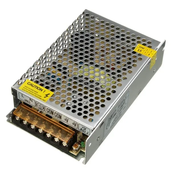
12V 10A SMPS – 120W DC Metal Power Supply
A reliable 12V 10A power supply for driving LED strips, motors, and other loads through your MOSFET switch circuit. Good quality with short-circuit protection.
Frequently Asked Questions
Can I drive the IRF540N directly from an Arduino 5V pin?
Yes, but with limitations. At Vgs = 5V, the IRF540N has Rds_on of approximately 150–250mΩ (versus 44mΩ at 10V). For loads under 2A, the power dissipation (P = I² × Rds) is manageable (0.6–1W) with a small heatsink. For loads above 2–3A, use a logic-level MOSFET (IRLZ44N, IRLB8721) rated at Vgs = 4.5V or 5V.
What is the Miller effect and why does it matter for MOSFET switching?
The Miller effect is the amplification of the gate-drain capacitance (Cgd) during switching. As the drain voltage changes rapidly, current flows back through Cgd into the gate, temporarily halting the gate voltage change (creating the “Miller plateau” on gate voltage waveforms). During this plateau, the MOSFET transitions through the linear region with maximum power dissipation. A stronger gate driver (more current, lower Rg) charges through the plateau faster, reducing switching losses.
My MOSFET gets very hot even though it is fully ON. Why?
Possible causes: (1) Gate voltage is insufficient — the MOSFET is not fully in linear region, Rds_on is elevated. Increase Vgs. (2) The load current exceeds what the MOSFET can handle at the ambient temperature — check derating curves in the datasheet. (3) The switching frequency is too high — switching losses (proportional to frequency) dominate. Reduce frequency or use a faster MOSFET. (4) Inadequate heatsink — add a larger heatsink and use thermal paste.
Can a MOSFET switch AC loads?
A single MOSFET can only block voltage in one direction (the body diode conducts in the reverse direction). To switch AC loads, you need two MOSFETs in anti-series configuration (source pins connected together) for full AC blocking, or use a TRIAC/solid-state relay for simplicity. Never connect an inexpensive N-channel MOSFET directly across a mains AC supply — it will fail dangerously.
What is the purpose of the 10kΩ gate pull-down resistor?
It ensures the MOSFET stays firmly OFF when the gate drive signal is disconnected or floating. Without it, static charge, microcontroller startup states, or noise can accidentally turn ON the MOSFET. In PWM applications, it also helps discharge the gate quickly when the drive pin goes LOW, reducing on-time during turn-off transitions.
How do I switch a motor with a MOSFET?
For a DC motor running in one direction, use a single N-channel MOSFET in the same low-side configuration as the LED strip circuit, with a flyback diode (e.g., 1N5822 Schottky) across the motor terminals (cathode to V+). For bidirectional control, you need an H-bridge (four MOSFETs or an H-bridge IC like L298N or DRV8833). Always add the flyback diode — motor windings generate large reverse voltage spikes during switching.
Get LED strips, power supplies, and electronics components from Zbotic. Shop Power Electronics at Zbotic — fast delivery across India.


Add comment