
Inductors are one of the three fundamental passive components in electronics — yet they remain the least understood by beginners. While resistors and capacitors get plenty of attention, inductors quietly do some of the most important work in power supplies, radio filters, motor drivers, and signal processing circuits. This guide covers everything you need to know about inductor basics: what they are, how they work, their key parameters, and how they behave in real filter and power circuits.
What Is an Inductor?
An inductor is a passive electronic component that stores energy in a magnetic field when current flows through it. In its simplest form, it is a coil of wire — sometimes wound around a magnetic core material such as ferrite or iron powder. The symbol for an inductor in circuit diagrams is a series of loops or humps.
The defining property of an inductor is inductance, measured in Henries (H). In most practical electronics you will encounter microhenries (µH) and millihenries (mH). A typical inductor used in a DC-DC converter might be 10µH to 100µH, while inductors used in audio crossovers can be several millihenries.
Unlike a resistor, which dissipates energy as heat, or a capacitor, which stores energy in an electric field, an inductor stores energy magnetically — and releases it back into the circuit when needed. This property makes inductors indispensable in power conversion and signal filtering.
How Inductors Work: The Physics
The operation of an inductor is governed by Faraday’s Law of Electromagnetic Induction. When current flows through a coil of wire, it creates a magnetic field around the wire. If the current changes, the magnetic field changes, which in turn induces a voltage (called back-EMF) that opposes that change. This is described by:
V = L × (dI/dt)
Where V is the induced voltage, L is the inductance, and dI/dt is the rate of change of current. This equation tells us two critical things:
- Inductors resist changes in current. You cannot instantly change the current through an inductor — it always ramps up or down at a rate determined by the circuit.
- A larger inductance means a stronger opposition to current change. A 100µH inductor will change current more slowly than a 10µH inductor under the same voltage.
This behaviour is often described by saying inductors have inertia for current, just as a flywheel has inertia for mechanical rotation. When you apply voltage across an inductor, current builds up gradually. When you remove the voltage, the inductor tries to keep the current flowing — and if the circuit suddenly opens, it generates a large voltage spike (flyback voltage) to maintain that current flow.
Energy Storage in an Inductor
The energy stored in an inductor is given by:
E = ½ × L × I²
This means energy increases with the square of current. A 10µH inductor carrying 2A stores four times more energy than the same inductor carrying 1A. This relationship is critical when designing power circuits — it determines how much energy can be transferred per switching cycle.
Key Parameters: Inductance, Current Rating, DCR
When selecting an inductor for a circuit, you need to understand several key specifications:
1. Inductance Value (L)
The nominal inductance, usually specified at a particular frequency and current. For power inductors, the inductance often decreases at higher currents due to core saturation. Always check the inductance vs. current curve in the datasheet.
2. Rated Current / Saturation Current
Two current ratings matter: rated (RMS) current sets the thermal limit (how much current the inductor can handle before overheating), and saturation current sets the magnetic limit (the point where inductance drops significantly, usually by 20–30%). For power applications, stay well below saturation current.
3. DC Resistance (DCR)
The resistance of the wire winding itself. Lower DCR means less power loss. For efficiency-critical designs (battery-powered devices, high-current buck converters), choose inductors with DCR below 50mΩ if possible.
4. Self-Resonant Frequency (SRF)
Every inductor has parasitic capacitance between windings. Above the SRF, the component behaves capacitively instead of inductively. Always use an inductor well below its SRF — typically at less than one-tenth of the SRF for reliable inductive behaviour.
5. Quality Factor (Q)
Q = XL / R, where XL is the inductive reactance at the operating frequency. High Q inductors are preferred in RF and filter applications to minimise signal loss.
Types of Inductors
Inductors come in many physical forms, each suited to different applications:
Air-Core Inductors
Wound on non-magnetic formers or self-supporting. No core saturation possible. Used in RF circuits (MHz+ frequencies). Low inductance values (nH to a few µH).
Iron-Core Inductors
Wound on laminated iron cores. High inductance (mH to H range). Used in audio crossovers, transformers, and line filters. Not suitable for high frequencies.
Ferrite-Core Inductors
The most common type in modern electronics. Ferrite offers high permeability and low losses at switching frequencies (tens of kHz to several MHz). Used in DC-DC converters, EMI filters, and switch-mode power supplies (SMPS).
Toroidal Inductors
Wound on a donut-shaped core. The closed magnetic path reduces EMI leakage and provides very high inductance per turn. Popular in power supplies and audio equipment.
SMD Power Inductors
Surface-mount components for PCB assembly. Come in shielded and unshielded variants. Shielded inductors (e.g., the popular Bourns SRR series) radiate less EMI and are preferred in sensitive designs.
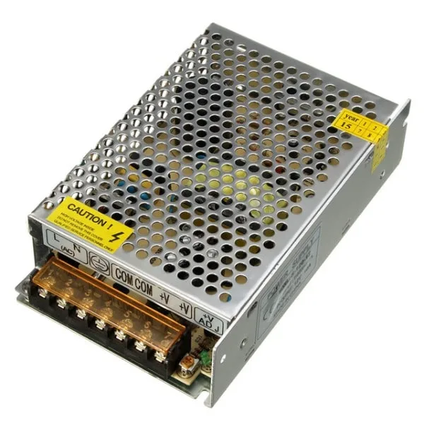
12V 10A SMPS – 120W DC Metal Power Supply
A switch-mode power supply that relies on an inductor at its core. Perfect for understanding real-world inductor applications in SMPS designs.
Inductors in Filter Circuits
One of the most important applications of inductors is in filter circuits. Because an inductor’s impedance increases with frequency (XL = 2πfL), it naturally blocks high-frequency signals while passing low-frequency ones. This is the basis of LC and RL filters.
RL Low-Pass Filter
A simple RL low-pass filter consists of an inductor in series with the load. At low frequencies, the inductor has low impedance and passes signals. At high frequencies, impedance rises and the signal is attenuated. The cutoff frequency is:
fc = R / (2π × L)
For example, with R = 1kΩ and L = 100mH: fc = 1000 / (6.28 × 0.1) ≈ 1592 Hz
LC Low-Pass Filter
Combining an inductor with a capacitor gives a second-order LC low-pass filter with a much sharper roll-off (40 dB/decade versus 20 dB/decade for RL). This is the standard output filter used in DC-DC converters to smooth the pulsed output voltage into clean DC.
fc = 1 / (2π × √(LC))
LC Band-Pass and Band-Stop Filters
LC circuits can also be tuned to pass or reject a specific frequency band. A series LC circuit has minimum impedance at resonance (band-pass), while a parallel LC circuit has maximum impedance at resonance (band-stop or notch filter). These are the building blocks of radio tuner circuits, audio equalizers, and EMI filters.
EMI Filter Inductors
In power electronics, common-mode chokes (a type of coupled inductor) suppress electromagnetic interference on power lines. They are found in virtually every SMPS, motor drive, and USB charger. The inductor presents high impedance to noise signals while allowing the intended DC or low-frequency AC current to pass freely.
Inductors in Power Circuits
Inductors are the energy-transfer element in virtually all modern DC-DC power converters. Understanding this application is key to working with power electronics.
Buck (Step-Down) Converter
In a buck converter, a switch (MOSFET) connects the input voltage to the inductor for a controlled on-time, then disconnects. The inductor stores energy during the on-time and releases it to the output during the off-time. The output capacitor smooths the residual ripple. The output voltage is determined by the duty cycle:
Vout = Vin × D (where D = ton / T)
The inductor value determines the current ripple: a larger inductor gives less ripple but is physically larger and more expensive. Typical switching frequencies are 100kHz–2MHz, allowing small inductors (1–47µH).
Boost (Step-Up) Converter
In a boost converter, the inductor stores energy when the switch is ON (connecting it to ground through the switch). When the switch turns OFF, the inductor’s back-EMF adds to the input voltage, driving current through a diode to the output at a higher voltage. Boost converters power white LEDs from a single battery cell, generate high voltages for displays, and more.
Flyback Converter
A transformer-coupled inductor (flyback transformer) allows galvanic isolation between input and output. The primary winding stores energy when the switch is ON; it transfers that energy to the secondary winding when the switch is OFF. Most phone chargers and laptop power adapters use flyback topology.
Energy Storage in UPS and Battery Systems
Large inductors (sometimes called reactors) limit inrush current, smooth charging current in battery chargers, and reduce di/dt stress in UPS systems. Their ability to oppose rapid current changes protects sensitive components from switching transients.
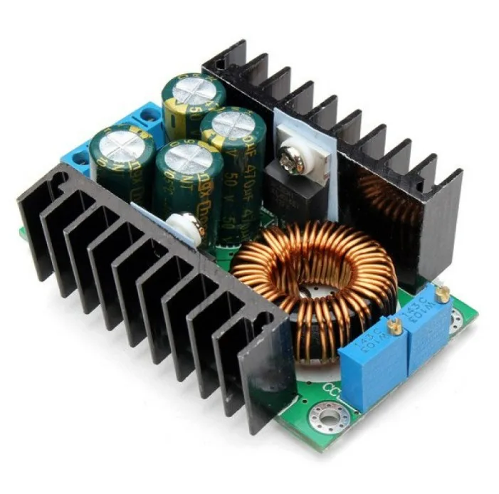
300W 10A DC-DC Step-Down Buck Converter Module
A real buck converter module that uses an inductor for energy transfer. Great for experimenting with inductor behaviour in power conversion circuits.
Inductor vs Capacitor: Key Differences
| Property | Inductor | Capacitor |
|---|---|---|
| Energy storage | Magnetic field | Electric field |
| Opposes changes in | Current | Voltage |
| Impedance vs frequency | Increases (XL = 2πfL) | Decreases (XC = 1/2πfC) |
| Passes DC steadily | Yes (after transient) | No (blocks DC) |
| Phase relationship | Voltage leads current by 90° | Current leads voltage by 90° |
| Filter role | Series element (blocks AC noise) | Shunt element (bypasses AC noise) |
Practical Tips for Using Inductors
- Never leave an inductor circuit open while current is flowing. The resulting flyback voltage spike can destroy transistors, MOSFETs, and other components. Always include a flyback diode (freewheeling diode) across inductive loads such as relay coils and DC motors.
- Derate inductor current in hot environments. As temperature rises, DCR increases and core losses worsen. Run inductors at no more than 70–80% of their rated current in high-ambient-temperature designs.
- Choose the right core material for your frequency. Ferrite cores for switching frequencies (100kHz+), powdered iron for medium frequencies, laminated iron for 50/60Hz line applications.
- Keep switching-regulator inductors away from sensitive analog circuits. Inductors radiate magnetic fields; use shielded inductors or orient them to minimise coupling into sensitive areas of your PCB.
- Check inductance at operating current. Many power inductors saturate at 50–70% of their rated peak current, causing inductance to drop sharply. Use the datasheet’s L vs. I curve to confirm adequate inductance at your peak operating current.
- Use a multimeter’s inductance mode or an LCR meter to verify unknown inductors. Wire-wound components can look similar but have very different values.
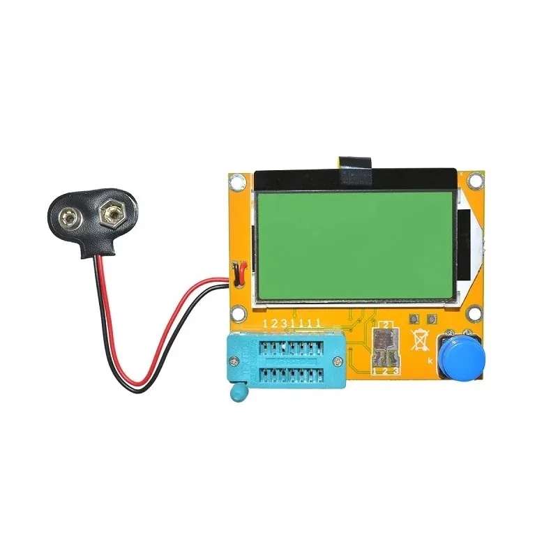
LCR-T4 Transistor Tester – Measures L, C, R, ESR
Identify and measure inductors, capacitors, and resistors quickly. Essential for verifying components before use in your inductor projects.
Frequently Asked Questions
What is the main purpose of an inductor in a circuit?
Inductors store energy in a magnetic field and resist changes in current. Their main roles are filtering AC noise from DC power rails, transferring energy in DC-DC converters (buck, boost, flyback), and forming resonant circuits with capacitors for frequency selection.
What happens if an inductor saturates?
When an inductor saturates, its core can no longer support more magnetic flux. Inductance drops sharply, often by 50–80% or more. In a switching converter, this means much higher current ripple, reduced efficiency, and potential damage to the switching transistor due to excessive peak current.
Can I use any inductor in a DC-DC converter?
No. Power inductors must have adequate current rating (above peak inductor current), low DCR (for efficiency), appropriate inductance value (sets ripple), and a core material suitable for the switching frequency. General-purpose inductors or RF chokes are usually unsuitable for power conversion.
What is the difference between an inductor and a transformer?
A transformer has two or more coupled windings and transfers energy from primary to secondary by mutual inductance. An inductor is a single winding that stores and releases energy. In a flyback converter, the component is technically a coupled inductor (also called a flyback transformer), but it works by storing energy in the primary, then releasing it to the secondary — unlike a true transformer which transfers energy continuously.
Why does an inductor generate a voltage spike when current is interrupted?
According to V = L × dI/dt, if current drops to zero very quickly (large dI/dt), a very large voltage is generated. In a relay coil circuit with no flyback diode, interrupting the coil current can generate hundreds of volts — easily destroying a transistor rated for 40V. Always use a flyback diode across any inductive load.
How do I calculate the inductance needed for a buck converter?
The standard formula for a buck converter inductor is: L = (Vin – Vout) × D / (fsw × ΔIL), where D is duty cycle (Vout/Vin), fsw is switching frequency, and ΔIL is the desired current ripple (typically 20–30% of average output current). Plug in your numbers and select the nearest standard value.
Zbotic stocks a wide range of power supplies, buck converters, and passive components for your electronics projects. Browse Electronics Components on Zbotic and get fast delivery across India.


Add comment