
Isolation Amplifier: Signal Isolation in High Voltage Systems
An isolation amplifier circuit is an essential building block in any system where you need to measure or transmit signals across a safety barrier — between high-voltage power electronics and low-voltage measurement circuitry, between mains-connected equipment and patient-monitoring devices, or between ground-loop-prone industrial sensors and data acquisition systems. Isolation amplifiers pass signal information while blocking DC and low-frequency common-mode voltages that could otherwise damage sensitive electronics or create safety hazards. This guide explains the principles, key specifications, and practical design guidance for isolation amplifiers in Indian maker and industrial applications.
What Is an Isolation Amplifier?
An isolation amplifier (iso-amp) amplifies a differential signal while providing electrical isolation between its input and output. The isolation barrier — implemented using optical, capacitive, or magnetic coupling — blocks DC and prevents dangerous voltages from reaching the measurement side of the circuit.
Unlike a standard differential amplifier (like an instrumentation amplifier), which rejects common-mode voltages up to a few volts or tens of volts, an isolation amplifier can handle common-mode voltages of hundreds or even thousands of volts — safely transmitting the small differential signal riding on top of them.
Isolation amplifiers are specified by:
- Working isolation voltage: Maximum continuous voltage across the barrier (e.g., 250V RMS, 1000V peak)
- Transient isolation voltage: Peak voltage the barrier can withstand momentarily (e.g., 3500V peak per IEC 60601-1)
- Withstand voltage (Hi-Pot): Voltage applied during dielectric test (1 minute, no breakdown)
- CMRR: Common Mode Rejection Ratio — how well it rejects the high common-mode voltage
Why Signal Isolation Is Necessary
Safety — Protecting Personnel
In medical equipment, isolation prevents leakage current from reaching patients. IEC 60601-1 sets the patient leakage current limit at 10µA for Type CF (cardiac floating) equipment. An isolation amplifier with >1500V working isolation ensures there’s no conductive path from mains-powered circuitry to electrodes touching the patient.
Protecting Expensive Electronics
When measuring current or voltage in a 3-phase inverter (common in Indian industrial installations with 415V three-phase power), any ground fault or measurement error could connect your 3.3V ADC directly to 415V. Without isolation, this destroys the ADC, the microcontroller, and potentially the entire control board. An isolation amplifier limits damage to the (replaceable) isolation IC itself.
Breaking Ground Loops
In systems where the sensor and measurement equipment have different ground potentials (common in long cable runs, industrial environments, and multi-instrument setups), a ground loop causes 50/60Hz interference that can overwhelm the actual signal. Isolation breaks the conductive path, eliminating the ground loop entirely.
High-Side Current Sensing
Measuring current in the high-side of a half-bridge or full-bridge motor driver requires sensing a signal riding on the switching node voltage — which swings between GND and VBUS (typically 12–400V). An isolation amplifier allows the current sense signal to be referred to the high-side rail while the ADC reads a ground-referenced output.
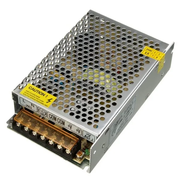
12V 10A SMPS – 120W DC Metal Power Supply
Industrial-grade SMPS for powering isolation amplifier circuits and data acquisition systems. Separate floating supply for the isolated input side of your design.
Types of Isolation: Optical, Capacitive, and Magnetic
Optocoupler-Based Isolation Amplifiers
The earliest isolation amplifiers used LED-photodiode pairs (optocouplers) to transmit analog signals across the isolation barrier. The input signal modulates the LED current, and the photodiode converts it back. However, basic optocouplers are highly nonlinear and temperature-sensitive — not suitable for precision analog measurement.
Linear optocoupler ICs (like the IL300 or HCNR201) use a dual-photodiode feedback topology to achieve linearity better than 0.01%. These are still used in audio isolation and precision analog circuits where cost matters more than bandwidth.
The ISO124 from Texas Instruments is a classic optically-isolated instrumentation amplifier: ±0.5% max nonlinearity, 50kHz bandwidth, ±15V supplies, 1500V isolation — widely used in industrial and medical designs.
Capacitive Isolation (Sigma-Delta Modulators)
Modern isolation amplifiers like the ACPL-C87A (Broadcom) and AMC1300 (Texas Instruments) use on-chip capacitive isolation with sigma-delta modulation. The input signal is digitized by a sigma-delta ADC on the input (high-voltage) side, and the resulting bit-stream is transmitted across the capacitive barrier using high-frequency carrier modulation. The output side demodulates and reconstructs the analog signal.
Advantages of capacitive isolation:
- Higher bandwidth (100kHz to several MHz)
- Lower power consumption
- Integration of ADC function for direct digital output
- Better reliability (no LED aging)
- CMRR > 120dB at 50Hz
Magnetic (Transformer-Based) Isolation
Some isolation amplifiers use on-chip micro-transformers (e.g., Texas Instruments’ iCoupler technology) to transmit signals. This approach offers high transient immunity and excellent common-mode rejection, making it preferred for gate driver and power converter control applications where fast common-mode transients (dV/dt up to 50–100kV/µs) occur.
Key Specifications Explained
Isolation Voltage Classes
IEC 61010-1 defines working voltages and pollution degrees that determine required creepage and clearance distances:
- Basic isolation: Single protection against electric shock. Minimum for general industrial use
- Reinforced isolation: Double the insulation — required for medical, consumer mains equipment
- Functional isolation: No shock protection — used only for circuit function (e.g., ground loop breaking)
Common Mode Rejection Ratio (CMRR)
Expressed in dB, CMRR of an isolation amplifier indicates how much the output rejects the high common-mode voltage. For a 1000V common-mode signal with 120dB CMRR:
Voutput_error = 1000V / 10^(120/20) = 1000V / 1,000,000 = 1mV
This 1mV error is acceptable when measuring a 100mV signal, but would be unacceptable for a 1mV signal — illustrating why CMRR specification must be considered relative to the signal amplitude.
Isolation Capacitance
The barrier capacitance (typically 1–10pF across the isolation barrier) limits high-frequency common-mode rejection. At 50Hz mains frequency, a 2pF capacitance presents 1.6GΩ impedance — excellent. At 10kHz switching frequency, the same capacitance presents only 8MΩ — still good but leakage current increases. For EMC-sensitive designs, minimize barrier capacitance by choosing ICs with the lowest specified CISO.
10CM Female To Female Breadboard Jumper Wires – 40Pcs
High-quality jumper wires for connecting isolation amplifier evaluation boards to Arduino or STM32 development boards during prototyping and testing.
Popular Isolation Amplifier ICs
AMC1300 (Texas Instruments)
Designed specifically for shunt-based current sensing in motor drives and solar inverters. Features: ±250mV input range (perfect for shunt resistors), 85dB CMRR, 2MHz bandwidth, ±5V isolated supply required on input side, 5V single supply on output side, 3000V reinforced isolation. Available in SOIC-8 with 8mm creepage. Excellent choice for Indian industrial drives at ₹150–300 per IC.
ACPL-C87A (Broadcom)
Optically isolated sigma-delta ADC amplifier with integrated digital output (serial bit-stream). Input: ±200mV for shunt measurement. Isolation: 2500V. Available in eSOP-6 package. Ideal for motor drive current sensing where the microcontroller can process the bit-stream digitally.
ISO124 (Texas Instruments)
Classic analog isolation amplifier, voltage input/output. Gain = 1, bandwidth 50kHz, ±0.5% nonlinearity, 1500V isolation. Requires ±15V on both sides. Best for legacy designs and audio applications where the simpler analog interface is preferred over digital methods.
INA300 Series (Texas Instruments)
Not an isolation amp but worth mentioning: the INA300 is a dedicated current-sense amplifier with integrated comparator and isolated switching capability — a compact solution for motor protection circuits.
Isolation Amplifier for High-Side Current Sensing
One of the most common applications in Indian electronics projects is measuring the current in a DC motor driver or battery charger. Here’s a practical circuit using a shunt resistor + isolation amplifier:
Design for 48V DC Motor Current Sensing
- Shunt resistor: 10mΩ (Rshunt) in series with motor positive terminal. At 10A, voltage across shunt = 100mV
- Isolation amplifier: AMC1300 with ±250mV input range — 100mV well within range
- Isolated supply: Small isolated DC-DC converter (ADUM5010 or off-shelf 1W isolator module) provides ±5V to AMC1300 input side from the 48V side
- Output: AMC1300 produces 0–4.5V analog signal on the 3.3V/5V ground-referenced output side, directly readable by STM32 ADC
- Isolation withstand: AMC1300 handles the full 48V common-mode plus any transient spikes from motor switching
Total cost for this solution: AMC1300 ≈ ₹200, 1W isolator module ≈ ₹120, shunt resistor ≈ ₹30. Total ₹350 for a fully isolated current sensing solution that protects a ₹5,000+ microcontroller board.
PCB Layout Considerations for Isolation Amplifiers
Even the best isolation amplifier IC will fail to meet its specifications if the PCB layout doesn’t respect the isolation requirements.
Creepage and Clearance
The physical distance between input-side and output-side conductors on the PCB must be sufficient for the rated isolation voltage. For 1000V isolation (Pollution Degree 2, Basic insulation per IEC 61010-1):
- Clearance: 1.5mm (through air)
- Creepage: 4.0mm (along PCB surface)
For reinforced insulation (medical, 2× creepage/clearance): 8.0mm creepage minimum. This is why isolation amplifier ICs have packages specifically designed with wide body spacing (8mm between input and output pins).
Slot Cuts in PCB
To increase creepage distance without making the PCB larger, route a slot (gap) in the PCB between the input and output sides of the isolation amplifier. This forces surface creepage current to travel around the slot edge, effectively doubling the creepage distance for the slot length.
Separate Power Planes
Never share power or ground planes across the isolation barrier. Use separate copper fills on both sides, each referenced to their respective grounds. The barrier area (under the isolation IC) should have no copper on any layer — not even inner layers of a multilayer PCB.

10×10cm Universal PCB Prototype Board Single-Sided
Single-sided prototype board for building and testing isolation amplifier circuits. 2.54mm hole pitch, 10×10cm size gives plenty of room for high-voltage isolation layouts.
Frequently Asked Questions
Can I use a regular op-amp instead of an isolation amplifier?
Only if the common-mode voltage is within the op-amp’s supply voltage range (typically ±15V for standard op-amps). For high-voltage applications (>50V common mode), a standard op-amp will be destroyed. An isolation amplifier is the correct solution when the signal rides on a high common-mode voltage.
What is the difference between an isolation amplifier and an optocoupler?
Standard optocouplers (like PC817) are designed for digital signals — they have highly nonlinear LED/photodiode characteristics that introduce significant distortion in analog signals. Linear optocouplers (IL300, HCNR201) and dedicated isolation amplifier ICs are specifically designed for accurate analog signal transmission. Never use a digital optocoupler for analog isolation without appropriate linearisation.
How do I power the isolated input side?
The input side of an isolation amplifier needs a separate floating power supply referenced to the high-voltage ground. Options: 1W isolated DC-DC converter module, transformer-based supply, or buy an isolation amplifier IC with integrated isolated power (like the AMC3301 which includes an internal DC-DC converter — no separate isolated supply needed).
What isolation voltage do I need for 230V mains measurement?
For basic isolation in industrial equipment, 1500V is a common standard. For medical equipment or where reinforced insulation is required, 3000–4000V withstand is needed. The working isolation voltage (continuous) should be at least 2× the peak AC voltage: for 230V RMS, peak is 325V, so 1000V working isolation provides a 3× safety margin.
Are isolation amplifiers available in India?
Yes — the AMC1300, ISO124, and ACPL-C87A series are available from Indian distributors (Mouser India, Digikey, Robu.in). Prices range from ₹150–500 per IC. For hobbyist applications, evaluation modules with these ICs are available on Amazon India at ₹400–800.
Designing with high voltages? Zbotic has the passive components, power modules, and prototyping tools you need to build safe, reliable isolation circuits. From precision resistors for accurate signal conditioning to universal prototype boards for layout testing — visit our Electronics Components collection today.


Add comment