
Table of Contents
- Introduction: Two Ways to Detect Magnetism
- How Reed Switches Work
- How Hall Effect Sensors Work
- Key Differences at a Glance
- Switching Speed and Response Time
- Power Consumption
- Durability and Lifespan
- Magnetic Sensitivity and Range
- Temperature Performance
- Output Signals and Interfacing
- Applications: When to Use Which
- Wiring Examples for Arduino
- Cost Comparison in India
- FAQ
Introduction: Two Ways to Detect Magnetism
Whether you are building a door alarm system, a bicycle speedometer, a rotary encoder, a flow meter, or a proximity switch, you will inevitably face the reed switch vs Hall effect sensor choice. Both detect the presence of a magnetic field and produce an electrical output, but they achieve this through entirely different physical principles — and that difference has profound implications for where and how you use them.
Reed switches have been around since 1936, invented at Bell Telephone Laboratories. Hall effect sensors date their widespread commercial use to the 1970s. Today, both technologies thrive side by side, each dominating specific application segments. This guide provides an in-depth comparison to help Indian electronics engineers, hobbyists, and product designers make the right choice for their specific needs.
How Reed Switches Work
A reed switch is an electromechanical component. Inside a hermetically sealed glass tube (the reed), two thin ferromagnetic metal blades (reeds) are positioned with a tiny overlapping gap. When a permanent magnet or electromagnet comes close enough, the blades are magnetised and attract each other, snapping together to close the electrical circuit. Remove the magnet, and the spring tension in the blades pulls them apart, opening the circuit.
The operating mechanism is entirely mechanical — there are no semiconductors. The switch itself is a passive element: it does not need a power supply. The contact closure simply connects or disconnects whatever circuit is wired to its two terminals, just like a mechanical push-button but activated by a magnet rather than a finger.
Types of Reed Switches
- SPST-NO (Single Pole Single Throw, Normally Open): Most common. Contacts open with no magnet, close with magnet. Used in door sensors, position detection.
- SPST-NC (Normally Closed): Contacts closed with no magnet, open with magnet. Used in fail-safe applications — alarm triggers if the magnet is removed.
- SPDT (Single Pole Double Throw): Has a common terminal, NO, and NC. Rare, more expensive.
- Latching Reed Switches: Use two reed elements and a ferrite magnet to maintain state without external magnetic field. Used in low-power memory applications.
Reed switches are rated by their Ampere-Turn (AT) sensitivity — the minimum magnetomotive force needed to actuate them, typically 15–60 AT. They are also rated for maximum switched current (10 mA to 5 A depending on size) and voltage (100V to 1000V for high-voltage types).
How Hall Effect Sensors Work
A Hall effect sensor is a solid-state semiconductor device. When current flows through a thin semiconductor slice (the Hall element) and a magnetic field is applied perpendicular to the current, the Lorentz force deflects charge carriers to one side of the element, creating a small voltage differential — the Hall voltage — transverse to both current and field direction. This was discovered by Edwin Hall in 1879.
The Hall voltage is extremely small (microvolts to millivolts), so Hall effect ICs integrate the Hall element with an amplifier, comparator, and often a Schmitt trigger (for digital output) or a linear amplifier (for analog output) on a single silicon die.
Types of Hall Effect Sensors
- Digital Unipolar: Switch on (output LOW) when the south pole of a magnet exceeds the threshold; switch off when removed. AH3503, 44E, SS41F.
- Digital Bipolar (Latch): Turn on with south pole, stay on until north pole is applied. Essential for brushless DC motor commutation. HAL825, SS360.
- Linear (Analog): Output voltage proportional to field strength, centered at Vcc/2 with no field. TLE4905L, A1302. Used for current sensing, position, and angle measurement.
- 2D / 3D Hall: Measure field in two or three axes. Used for joystick position and contactless knob encoding.
Key Differences at a Glance
| Feature | Reed Switch | Hall Effect Sensor |
|---|---|---|
| Operating Principle | Electromechanical | Solid-state semiconductor |
| Requires power supply? | No (passive) | Yes (2.7–24V typical) |
| Max switching speed | ~1,000 Hz | >100,000 Hz |
| Mechanical wear | Yes (10⁷–10⁸ cycles) | None — unlimited cycles |
| Vibration / shock sensitivity | Fragile (glass tube) | Highly robust |
| Contact bounce | Yes — needs debouncing | No — clean digital edge |
| Galvanic isolation | Yes — contacts fully isolated | No (common ground) |
| Analog output possible | No | Yes (linear types) |
| Detects field polarity | No | Yes (bipolar types) |
| Operating temperature | −40°C to +125°C | −40°C to +150°C (some to +200°C) |
| Cost (India) | ₹5 – ₹80 | ₹15 – ₹200 per IC |
Switching Speed and Response Time
This is one of the starkest differences. A typical reed switch can reliably operate up to about 500–1,000 operations per second (Hz). Beyond this, the reed blades’ mechanical inertia prevents them from completing a full open-close cycle. This limits reed switches to relatively slow applications — door open/close detection, reed-based flow meters (typically 0.5–20 Hz pulse rate), and similar.
Hall effect sensors, being solid-state, have no moving parts and are limited only by their IC’s propagation delay — typically 1–10 microseconds, corresponding to switching rates of 100 kHz or higher. This makes them the only viable choice for:
- Brushless DC motor commutation (thousands of RPM)
- High-speed rotary encoders
- Automotive ABS wheel speed sensors (measuring small teeth on a ring gear at highway speed)
- High-frequency current sensing
Power Consumption
Reed switches consume zero quiescent current — they are passive contacts. The only power involved is in the circuit being switched. This makes them ideal for ultra-low-power battery applications where minimising standby current is critical, such as a door-open detector on a coin-cell powered burglar alarm that might need to last 5 years on a single CR2032 battery.
Hall effect sensor ICs draw quiescent current ranging from 2–10 mA for standard grades down to 1–50 μA for dedicated ultra-low-power variants (e.g., Allegro A1120 at 50 μA, Texas Instruments DRV5010 at 1.8 μA). Even at 1.8 μA, a CR2032 (240 mAh) would last about 15 years — so power is not always a barrier to Hall sensors in battery applications.
Durability and Lifespan
Reed switches are rated for 10 million to 100 million operations depending on the load switched. Without load (dry switching), lifespan can extend to 10 billion operations. However, when switching significant currents (especially inductive loads), contact erosion can dramatically shorten life to 1–5 million operations.
Additionally, reed switch glass tubes are fragile — they crack under mechanical shock or vibration, and should never be soldered with excess heat. Handle them gently; they are not suitable for high-vibration automotive or industrial environments without careful mechanical mounting.
Hall effect sensors have no wear mechanism. They are solid silicon ICs with an expected lifespan measured by MTTF (Mean Time To Failure) from thermal and ESD stress, typically quoted as billions of hours. They survive vibration, shock, and mechanical stress that would instantly destroy a reed switch. Automotive-grade Hall sensors (e.g., AEC-Q100 qualified) are rated for 150°C junction temperature and 15-year vehicle lifetimes under harsh under-hood conditions.
Magnetic Sensitivity and Range
Reed switches typically activate with magnetic fields of 10–50 mT at the reed, requiring a magnet placed 5–20 mm away depending on magnet strength. The glass enclosure limits field penetration somewhat. They are omnidirectional to the field orientation — any pole activates them (except NC types which open with any pole).
Hall effect ICs can be extremely sensitive, detecting fields as low as 1–5 Gauss (0.1–0.5 mT) for high-sensitivity linear types. Digital switching types typically have operate thresholds from 5–200 Gauss. Bipolar latching types distinguish north from south pole. Some Hall ICs include concentrator magnets in their packaging to enhance sensitivity for specific applications. The effective detection range extends from a few mm to several centimetres depending on magnet strength and sensor sensitivity.
Temperature Performance
Both technologies operate across wide temperature ranges. Reed switches: −40°C to +125°C standard. The glass-to-metal seals and magnetic blade properties shift slightly with temperature, causing small variations in operate/release fields.
Hall effect sensors: standard grades −40°C to +125°C, automotive grades up to +150°C, and specialty high-temperature grades to +200°C or beyond. At very high temperatures, the Hall element’s sensitivity changes with temperature — high-quality ICs include on-chip temperature compensation circuits to maintain accuracy across the operating range.
Output Signals and Interfacing
Reed Switch: Pure mechanical contact — completely passive. Can be wired as a pull-up with a resistor to a digital input pin, or used to switch mains voltage (rated types), or switch low-level signals. Requires debounce code or hardware debounce circuit (RC filter + Schmitt trigger).
Hall Effect (Digital): Open-drain NPN output — needs pull-up resistor to Vcc. Output goes LOW when activated, HIGH when not (active-low convention). Clean switching with internal Schmitt trigger hysteresis — no debounce needed. Can directly interface with Arduino, ESP32, or PLC digital inputs.
Hall Effect (Analog/Linear): Voltage output proportional to field. At zero field, output = Vcc/2. With south pole, output increases toward Vcc; north pole, output decreases toward GND. Connect directly to Arduino analogRead(). Enables measurement of field strength, current (via a shunt or busbar), or mechanical position.
Applications: When to Use Which
Use a Reed Switch When:
- You need galvanic isolation — switching a high-voltage circuit from a low-voltage controller without any ground connection between them
- The application has ultra-low duty cycle (e.g., a door sensor that triggers once a day) and battery life is paramount with no power budget for a sensor IC
- You are switching mains-voltage signals directly (reed relays rated for 1000V exist)
- The design requires extreme simplicity — no supply decoupling, no pull-up, no code; just two wires
- Operating temperature is below −55°C (deep cold environments where Hall ICs fail)
Use a Hall Effect Sensor When:
- Switching speed exceeds 1 kHz (motor control, encoders, flow meters with high pulse rates)
- The environment has vibration or shock that would break a reed switch glass tube
- You need to detect magnetic field polarity or strength (linear measurement)
- The sensor is in a location where mechanical replacement is difficult — Hall ICs last indefinitely
- The design uses through-hole or SMD components on a PCB and needs a small footprint
- You want clean, bounce-free digital output without debounce hardware or software
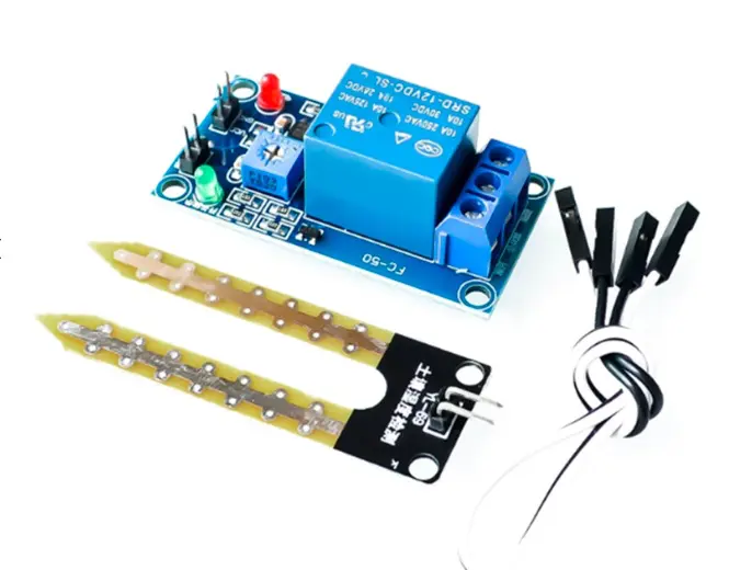
5V 12V Soil Moisture Sensor Relay Control Module
When a reed switch output needs to control a higher-current load (motor, solenoid), add a relay module like this for clean switching without IC damage.
Wiring Examples for Arduino
Reed Switch with Arduino
// Reed Switch on Digital Pin 2 with debounce
const int REED_PIN = 2;
int lastState = HIGH;
int stableState = HIGH;
unsigned long lastDebounceTime = 0;
const unsigned long DEBOUNCE_DELAY = 50; // ms

void setup() {
  Serial.begin(9600);
  pinMode(REED_PIN, INPUT_PULLUP); // internal pull-up
}

void loop() {
  int reading = digitalRead(REED_PIN);
  if (reading != lastState) lastDebounceTime = millis();
  if ((millis() - lastDebounceTime) > DEBOUNCE_DELAY) {
    if (reading != stableState) {
      stableState = reading;
      Serial.println(stableState == LOW ? "MAGNET DETECTED" : "Magnet removed");
    }
  }
  lastState = reading;
}
Digital Hall Effect Sensor (e.g., 44E/A3144) with Arduino
// Hall Effect Sensor (A3144 or 44E) — no debounce needed
// Wiring: VCC→5V, GND→GND, OUT→pin3 via 10kΩ pull-up
const int HALL_PIN = 3;

void setup() {
  Serial.begin(9600);
  pinMode(HALL_PIN, INPUT); // external 10kΩ pull-up to 5V
}

void loop() {
  if (digitalRead(HALL_PIN) == LOW) {
    Serial.println("South pole detected!");
  } else {
    Serial.println("No magnetic field");
  }
  delay(100);
}
RPM Measurement with Hall Effect Sensor
// RPM counter — Hall sensor on interrupt pin
volatile unsigned long pulseCount = 0;
unsigned long lastCalcTime = 0;

void countPulse() { pulseCount++; }

void setup() {
  Serial.begin(9600);
  attachInterrupt(digitalPinToInterrupt(2), countPulse, FALLING);
}

void loop() {
  if (millis() - lastCalcTime >= 1000) {
    float rpm = pulseCount * 60.0; // 1 magnet per revolution
    pulseCount = 0;
    lastCalcTime = millis();
    Serial.print("RPM: "); Serial.println(rpm);
  }
}

BMP280 Barometric Pressure and Altitude Sensor
Add environmental context to your magnetic detection project. Combine BMP280 altitude/pressure data with Hall-effect based flow or position sensing for richer embedded system telemetry.
Cost Comparison in India
Reed switches in India typically cost ₹5–₹20 per piece for standard glass tube types, up to ₹80–₹200 for high-voltage or surface-mount versions. Reed relay modules with driver transistors cost ₹50–₹150.
Hall effect ICs: Common unipolar digital ICs like A3141, 44E, SS41 cost ₹15–₹40 per IC. Pre-assembled modules with pull-up resistor and LED on a small PCB are available for ₹30–₹80. Linear Hall sensors like A1302 cost ₹50–₹100 per IC. Higher-performance automotive-grade and latching ICs range from ₹100–₹500.
For most hobbyist applications in India, the cost difference is negligible. Choose based on application requirements, not price alone.
Frequently Asked Questions
Can a Hall effect sensor replace a reed switch directly?
Functionally, yes for most digital detection tasks, but not directly in all circuits. A Hall sensor needs a power supply and has an open-drain output; a reed switch is passive contacts. You cannot plug a Hall sensor directly into a circuit designed for a reed switch without adding a pull-up resistor and supply rail.
Which is better for a bicycle speedometer?
Both work. Reed switches were the traditional choice due to simplicity. Hall effect sensors (specifically unipolar digital types) are now preferred because they are more resistant to vibration and work reliably at higher wheel speeds, and produce cleaner pulses that don’t require debouncing.
Do reed switches work with electromagnets?
Yes. Reed switches are commonly used as the armature contacts inside reed relays, where a small electromagnet coil (driven by a transistor or relay driver IC) controls the contact opening and closing. This provides excellent galvanic isolation between control and switched circuits.
What magnet do I need for a Hall effect sensor?
Any permanent magnet with enough field strength — neodymium (N35–N52) magnets are the most commonly used due to their high field density in a small size. For digital unipolar Hall ICs, a 6×3 mm neodymium disc magnet held 5–10 mm from the sensor face is typically sufficient.
Can I use a reed switch for AC mains circuits?
Yes, provided you use a reed switch rated for the voltage and current involved. High-voltage reed switches are rated up to 1000V. For mains switching, use a reed relay module with a properly rated switch element — do not use standard low-cost hobby reed switches on mains circuits.
Why does my Hall sensor output flicker at the transition distance?
The Schmitt trigger inside the Hall IC has a hysteresis window between the operate (turn-on) and release (turn-off) threshold. If the magnet is positioned right at the boundary, thermal noise and magnetic field variation cause the output to oscillate. Move the magnet closer or farther away, or add hysteresis in software.
Conclusion
The reed switch vs Hall effect comparison is not a winner-takes-all contest. Reed switches remain unbeatable for galvanic isolation, passive operation, and simple low-frequency detection in clean environments. Hall effect sensors dominate everywhere that speed, durability, vibration resistance, or polarity detection matters.
Understanding both technologies makes you a more capable electronics designer. Many production products use reed switches for door/lid detection while simultaneously using Hall ICs for motor commutation — each technology in its optimal role. Explore Zbotic’s sensor range to find the right components for your next project.


Add comment