
When you need to measure the precise position of a moving shaft, piston, or mechanical component to within a few micrometres, the Linear Variable Differential Transformer—universally known as the LVDT—is the instrument of choice. You will find LVDTs measuring fuel injector stroke in automotive labs, monitoring turbine blade clearance in power plants, calibrating CNC machine-tool axes, and detecting structural settlement in civil engineering monitoring systems. In India, as manufacturing and research facilities modernise, LVDTs are increasingly appearing in quality labs and R&D workshops.
This guide explains how the LVDT works from the electromagnetic core outward, covers signal conditioning, explains wiring and calibration, and compares the LVDT to alternative linear-position technologies so you can choose the right sensor for your project.
1. What Is an LVDT?
An LVDT is a passive electromechanical transducer that converts the rectilinear (straight-line) displacement of its movable core into an AC voltage output. It achieves this without any electrical contact between the moving and stationary parts—the core floats inside a cylindrical bore surrounded only by air and coil windings. This contactless design is the secret to the LVDT’s exceptional durability: there is literally nothing to wear out mechanically.
Key specifications to know when selecting an LVDT:
- Stroke range: The total usable measurement range, e.g. ±2.5 mm, ±25 mm, ±250 mm
- Sensitivity: Output voltage per unit displacement, typically expressed as mV/V/mm (millivolts per volt of excitation per millimetre)
- Excitation frequency: Usually 50 Hz to 20 kHz; most units are optimised for 1–5 kHz
- Linearity: Deviation from a perfect straight line, expressed as ±% of full range; ±0.1% to ±0.5% is typical
- Operating temperature: Standard units −40°C to +125°C; high-temperature versions to +650°C
2. How the LVDT Works: Electromagnetic Principles
The LVDT body contains three coils wound on a non-magnetic hollow cylinder:
- Primary coil (P): Centre coil, energised by an AC excitation voltage (carrier signal)
- Secondary coil S1: Upper half, receives magnetically induced voltage
- Secondary coil S2: Lower half, receives magnetically induced voltage, connected in series opposition to S1
A cylindrical ferromagnetic core (usually nickel-iron alloy) slides freely inside the bore. This core is attached to the object whose position you want to measure—a piston rod, a shaft, a test probe.
The Null Position
When the core sits exactly at the geometric centre, it couples equally to S1 and S2. Since the secondaries are connected in series opposition (180° out of phase), their induced voltages cancel and the net output voltage is zero. This is the null point or electrical zero.
Positive Displacement
Move the core toward S1: S1 sees stronger magnetic coupling and generates higher voltage; S2 sees weaker coupling. The differential output (V_S1 − V_S2) is a positive AC voltage whose amplitude is proportional to displacement. The phase is in-phase with the excitation signal.
Negative Displacement
Move the core toward S2: the situation reverses. The output amplitude is again proportional to displacement, but the phase is 180° opposite to the excitation signal. A phase-sensitive demodulator uses this phase information to produce a signed DC voltage—positive for one direction, negative for the other.
The resulting input-output relationship is beautifully linear over the rated stroke. Linearity error arises only near the ends of stroke, which is why LVDTs are always operated within their specified range.
3. Types of LVDTs
Standard AC LVDT
Requires an external oscillator/demodulator circuit or dedicated signal conditioning module. Offers the highest accuracy and temperature stability because the user can tune the excitation frequency and amplitude to suit the application.
DC-DC LVDT (DC-Operated)
Integrates an oscillator and demodulator inside the sensor body. Input: 10–30V DC. Output: 0–5V, 0–10V, or ±10V DC. Plug directly into a PLC, data acquisition system, or microcontroller ADC. Simpler wiring, slightly lower accuracy than AC-AC types, ideal for industrial retrofits.
Half-Bridge LVDT
Uses only two coils (primary + one secondary), producing an output that is non-zero at null. Simpler construction, used in force and pressure sensors where zero force always has a known reference.
Spring-Loaded Probe LVDT
The core is attached to a spring-loaded probe tip. Press the tip against a surface; the spring force ensures contact. Used in surface-finish gauges, bore gauges, and go/no-go inspection fixtures.
Free-Core (Captive Core) LVDT
No spring return. The core is mechanically coupled to the target via a connecting rod. Requires external guidance to prevent core rotation. Used in precision linear motion stages.
4. Signal Conditioning and Demodulation
For an AC LVDT you need a signal conditioning module that performs three functions:
- Oscillator: Generates the AC excitation voltage at the correct frequency and amplitude (commonly 3 Vrms at 2.5 kHz)
- Differential amplifier: Amplifies the small differential output voltage (typically 1–50 mV at mid-range)
- Phase-sensitive demodulator (PSD): Detects whether the output phase leads or lags the excitation, producing a signed DC voltage proportional to displacement
Popular signal conditioning ICs include the AD598 (Analog Devices, dedicated LVDT controller), the AD698, and the MAX1450. The AD598 is a complete single-chip solution: feed in the LVDT primary and secondary windings, set the excitation frequency with an external capacitor, and the output is a clean DC voltage.
AD598 Simplified Connection
AD598 connections:
  OSC1/OSC2 → timing capacitor (sets excitation frequency)
  EXC A / EXC B → LVDT primary coil
  VA+/VA− → LVDT secondary coil S1
  VB+/VB− → LVDT secondary coil S2
  VOUT → 0–5V DC to ADC / PLC input
  VCC/VEE → ±15V supply

Frequency calculation:
  f_EXC = 1 / (2π × 1.1 × R_OSC × C_OSC)
  For 2.5 kHz: C_OSC = 4.7 nF with internal 10 kΩ R_OSC
Using a DC-DC LVDT with Arduino
If using a DC-operated LVDT with 0–5V output, connection is straightforward:
// DC-DC LVDT: 0–5V output → Arduino A0
// LVDT range: ±10 mm (0V = -10mm, 2.5V = 0mm null, 5V = +10mm)

const float V_REF = 5.0;
const float RANGE_MM = 20.0; // total range
const float NULL_VOLTAGE = 2.5; // mid-scale

void loop() {
  int raw = analogRead(A0);
  float voltage = raw * V_REF / 1023.0;
  float displacement_mm = (voltage - NULL_VOLTAGE) * (RANGE_MM / V_REF);
  Serial.print("Position: ");
  Serial.print(displacement_mm, 3);
  Serial.println(" mm");
  delay(100);
}
5. Wiring and Connections
LVDT connectors vary by manufacturer. The most common pinouts for 5-wire AC LVDTs are:
| Wire / Pin | Function | Connect To |
|---|---|---|
| Red (or 1) | Primary AC excitation HI | Oscillator output + |
| White (or 2) | Primary AC excitation LO | Oscillator output − |
| Yellow (or 3) | Secondary S1 HI | Demodulator input A+ |
| Green (or 4) | Secondary common (S1−=S2+) | Demodulator input A−/B+ |
| Blue (or 5) | Secondary S2 LO | Demodulator input B− |
Shielding: Always use shielded cable and connect the shield to earth at the signal conditioning end only (single-point grounding). LVDT output signals are millivolt-level AC and extremely susceptible to 50/60 Hz mains interference and radio-frequency noise. Run the LVDT cable away from power cables, motor drives, and relay panels.
6. Calibration Procedure
LVDTs are ratiometric sensors, but temperature drift and mechanical tolerances require calibration for precision work. The standard two-point calibration procedure:
- Mechanical setup: Mount the LVDT body rigidly. Attach the core to a precision micrometer or calibrated reference fixture. Ensure the core can travel the full rated stroke without binding.
- Null adjustment: Set the micrometer to the mechanical mid-stroke. Adjust the signal conditioner zero potentiometer until VOUT reads exactly 0 V (AC type) or mid-scale (DC type).
- Full-scale adjustment: Move the core to maximum positive stroke (+FS). Adjust the gain potentiometer until VOUT reads the expected full-scale voltage (e.g., +5V or +10V).
- Linearity check: Move the core in equal steps across the entire stroke. Record VOUT at each step. Plot and compare against the ideal straight line. Deviation should be within the datasheet linearity specification.
- Temperature coefficient check (optional): If operating in variable temperature conditions, place the LVDT in an oven, heat to operating extremes, and record zero and span drift. Apply software temperature compensation if needed.
7. Common Applications
Manufacturing Quality Control
LVDT gauging heads measure part dimensions on production lines at rates up to 1,000 parts per minute. A spring-loaded probe LVDT mounted in a gauging fixture checks bore diameter, thread depth, or surface flatness to micrometre accuracy. Results feed into SPC (Statistical Process Control) software for real-time quality monitoring.
Hydraulic and Pneumatic Cylinder Position Feedback
Linear actuators in injection moulding machines, hydraulic presses, and robotic arms require closed-loop position feedback. An LVDT mounted alongside the cylinder rod provides the position signal to the servo controller. Advantages over encoders: no rotating parts to fail, survives high vibration and hydraulic fluid environments.
Structural Monitoring
Civil engineers install LVDTs across expansion joints in bridges, on dam walls, and in building columns to detect structural movement. Long-stroke LVDTs (±100 mm to ±500 mm) with dataloggers record slow movements over months and years. The contactless operation and absence of moving parts means they function reliably for decades with zero maintenance.
Medical Devices
Hospital ventilators use LVDTs to measure bellows or piston stroke, controlling tidal volume delivery. Dental chairs use LVDTs for backrest position. MRI-compatible non-magnetic LVDT variants (using non-ferrous cores) operate safely inside high magnetic fields.
Geotechnical Instruments
Triaxial soil-testing apparatus uses LVDTs to measure sample deformation under load. Laboratory consolidometers track soil settlement to derive compressibility parameters. The sensors operate for weeks inside pressure cells without access for maintenance—ideal for LVDT’s zero-maintenance character.
8. LVDT vs. Other Linear Position Sensors
| Sensor Type | Accuracy | Range | Cost | Best For |
|---|---|---|---|---|
| LVDT | ±0.05–0.5% | ±0.5–250 mm | Medium–High | High accuracy, harsh env, infinite life |
| Linear Potentiometer | ±0.5–2% | 10–1000 mm | Low | Low cost, moderate accuracy |
| Magnetostrictive | ±0.01% | 25–7,600 mm | High | Very long stroke, absolute position |
| Optical Encoder | sub-µm | Limited by scale | Medium–High | Ultra-high resolution, clean environment |
| Ultrasonic (ToF) | ±1–3 mm | 20–8,000 mm | Low | Non-contact, long range, moderate acc. |
The LVDT’s unique selling point is the combination of high accuracy, infinite mechanical life, and operation in harsh environments (oil, vibration, temperature extremes) where optical or resistive sensors fail. For maker or hobbyist projects where ±1 mm is acceptable, a potentiometer or ultrasonic sensor is far cheaper and simpler.
9. Related Sensors at Zbotic
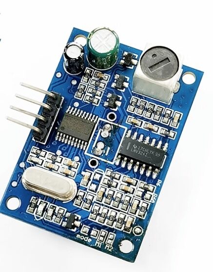
A86 JSN-SR04T Waterproof Ultrasonic Rangefinder Module V3.0
Non-contact distance measurement to 4.5m. Lower accuracy than LVDT but excellent for level sensing, liquid-tank monitoring, and coarse position detection.
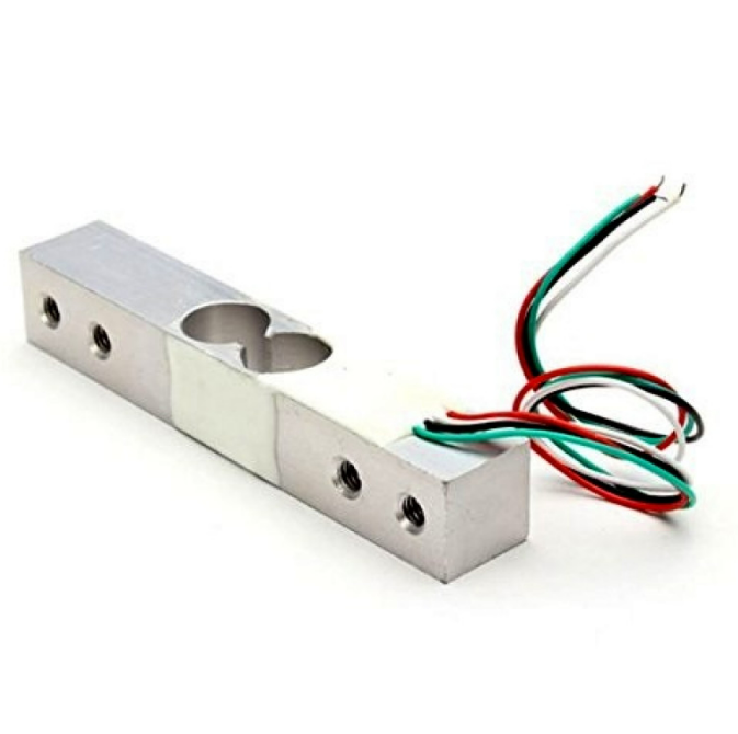
10Kg Load Cell – Electronic Weighing Scale Sensor
Like LVDTs, load cells use electromagnetic transduction principles (Wheatstone bridge) to measure mechanical quantities with high precision and repeatability.
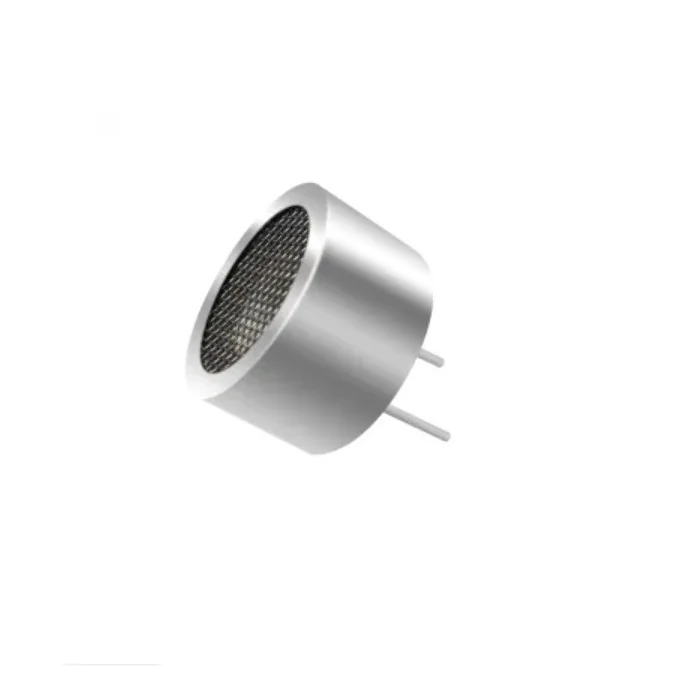
25kHz Ultrasonic Sensor Receiver T25 16mm
Low-frequency ultrasonic transducers for industrial proximity and distance measurement—complement to contact-type LVDT sensors in through-wall or submerged applications.
10. Frequently Asked Questions
Q: Can I use an LVDT with a microcontroller directly?
Not easily with a bare AC LVDT—you need a signal conditioning module (e.g., AD598 circuit or a standalone DIN-rail conditioner) that outputs 0–5V or 0–10V DC. DC-DC LVDTs have the conditioning built in and connect directly to any ADC. For Arduino/Raspberry Pi use, a DC-DC LVDT or a breakout module with AD598 is the right choice.
Q: What excitation frequency should I use?
Match the frequency to the signal conditioner’s specification. Common choices: 50 Hz (low bandwidth, low noise), 2.5 kHz (most general-purpose LVDTs), 10 kHz (faster dynamic response for vibration measurement). Higher frequency allows faster measurement updates but requires better-quality cabling and shielding.
Q: Why does my LVDT output drift over temperature?
Two causes: (1) Primary coil resistance changes with temperature, altering excitation current (use a voltage-source driver, not current-source). (2) Core and housing materials have different thermal expansion coefficients, shifting the null point. A ratiometric signal conditioner like the AD598 (which divides by primary voltage) largely eliminates cause 1. Cause 2 requires temperature compensation coefficients from the datasheet.
Q: How do I prevent core rotation in a free-core LVDT?
Use a non-rotating core guide bush, or select a captive-core LVDT where the core is constrained by an internal bearing. Rotation does not affect the electromagnetic measurement (the coils are cylindrically symmetric) but can damage the mechanical coupling to the target.
Q: Is there a maximum velocity for LVDT measurement?
The LVDT itself has no moving-contact speed limit. The constraint is your signal conditioning bandwidth. A 2.5 kHz excitation yields a maximum signal bandwidth of roughly 250 Hz (1/10 rule), so fast dynamics above 250 Hz motion cannot be resolved. For high-speed vibration measurement, use 10 kHz excitation and wide-bandwidth conditioning.
11. Conclusion
The LVDT remains one of the most elegant sensors in engineering: a simple electromagnetic principle produces a measurement that is repeatable, drift-resistant, and essentially immune to wear. Whether you are building a precision gauging jig, retrofitting position feedback to a hydraulic cylinder, or monitoring structural movement, understanding the LVDT’s working principle and signal conditioning requirements lets you deploy it correctly the first time.
For hobbyist and educational projects that demand linear position sensing at lower cost and complexity, the ultrasonic and load-cell sensors available at Zbotic offer a practical starting point. And when your project demands micrometre accuracy in a demanding industrial environment, the LVDT remains the benchmark to beat.
Explore our Sensors & Modules collection at Zbotic for ultrasonic rangefinders, load cells, current sensors, and more—shipped fast across India.


Add comment