
Measuring high currents accurately and safely is one of the most critical requirements in power electronics, electric vehicles, solar energy systems, and industrial motor control. The ACS758 family from Allegro MicroSystems is the go-to solution for high-current measurement, offering galvanically isolated sensing up to 200A with a simple analog voltage output that any microcontroller ADC can read. In this comprehensive guide, we cover everything from understanding Hall-effect current sensing fundamentals to wiring, calibration, Arduino integration, and real-world high-power applications.
What is the ACS758?
The ACS758 is a fully integrated Hall-effect based linear current sensor IC from Allegro MicroSystems. Unlike shunt-based current sensors that require a series resistor in the current path (causing power loss and requiring careful PCB layout), the ACS758 uses magnetic field sensing to measure current flowing through a thick copper conductor integrated directly into the IC package.
This design provides complete galvanic isolation between the high-current path and the measurement circuitry — the MCU-side electronics are completely isolated from the high-voltage/high-current load. This makes the ACS758 inherently safe for use in applications where the power side may be at mains voltage or high DC bus voltages.
The ACS758 outputs a ratiometric analog voltage proportional to current: at zero current, the output is at VCC/2 (typically 2.5V on a 5V supply). Positive current pushes the output towards VCC; negative current (reverse flow) pushes it towards GND. This bipolar operation allows measurement of both positive and negative current — critical for battery charge/discharge monitoring and motor drive applications.
How Hall-Effect Current Sensing Works
Hall-effect sensing exploits the Lorentz force. When current flows through the internal copper trace of the ACS758:
- The current creates a magnetic field proportional to its magnitude (Ampere’s law).
- A Hall-effect element positioned adjacent to the current path detects this magnetic field.
- The Hall voltage (proportional to field strength) is amplified and conditioned by internal circuitry.
- The conditioned output is presented as an analog voltage on the VIOUT pin.
The copper strap carrying the high current has very low resistance (typically 100 µΩ), causing minimal power dissipation even at 200A — only about 4W, versus the potentially hundreds of watts a high-wattage shunt resistor would dissipate. The Hall element and signal conditioning circuitry operate on the separate low-voltage supply (VCC), completely isolated from the power path.
ACS758 Variants: Which One to Choose?
| Part Number | Current Range | Sensitivity | Typical Use |
|---|---|---|---|
| ACS758LCB-050B | ±50A | 40 mV/A | Small EV, battery monitor |
| ACS758LCB-100B | ±100A | 20 mV/A | Solar inverters, motor drives |
| ACS758LCB-150B | ±150A | 13.3 mV/A | Industrial drives |
| ACS758LCB-200B | ±200A | 10 mV/A | High-power EVs, welders |
| ACS758ECB-050B-PFF-T | ±50A | 40 mV/A | PCB mount, through-hole bus |
The suffix B indicates bidirectional measurement. Unipolar variants (suffix U) only measure current in one direction (0 to full-scale) and output 0 to VCC rather than VCC/2 to VCC, offering double the sensitivity for unidirectional loads.

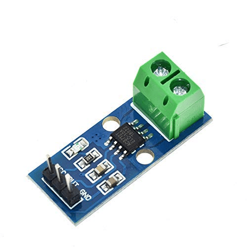
20A Range Current Sensor Module ACS712
For projects needing up to 20A measurement, the ACS712 module is a plug-and-play solution with identical Hall-effect technology at a lower price point.
ACS758 vs ACS712: Key Differences
Both sensors use the same Hall-effect principle, but they are designed for fundamentally different current ranges and applications:
| Feature | ACS712 | ACS758 |
|---|---|---|
| Max Current Range | 5A / 20A / 30A | 50A / 100A / 150A / 200A |
| Package | SOIC-8 (PCB mount) | Power tab / bus bar mount |
| Copper Conductor | Internal trace (thin) | Thick copper strap |
| Isolation Voltage | 2.1 kVRMS | 4.8 kVRMS |
| Bandwidth | 80 kHz | 120 kHz |
| Typical Application | Arduino projects, small robots | Solar, EVs, industrial |
Pinout and Electrical Characteristics
The ACS758 in the power tab package has the following connections:
- IP+ and IP-: The high-current input and output terminals (through the internal copper strap)
- VCC: Supply voltage, 3.0V to 5.5V (5V typical)
- GND: Ground reference for signal conditioning
- VIOUT: Analog output voltage proportional to measured current
- CF (filter): External capacitor pin for bandwidth reduction (leave open for max 120 kHz bandwidth; add 0.1µF for ~10 kHz)
Key electrical parameters at VCC = 5V:
- Quiescent output voltage (zero current): 2.5V ± 0.015V
- Sensitivity: 10–40 mV/A depending on variant (see table above)
- Accuracy: ±1.5% of full-scale over 0–85°C temperature range
- Response time: 4 µs (to 90% of final value)
- Operating temperature: -40°C to +150°C (IC) — current path temperature depends on current and ambient
Wiring ACS758 with Arduino
The signal-side connections are straightforward. The high-current path is wired in series with your load:
| ACS758 Signal Pin | Arduino Pin |
|---|---|
| VCC | 5V |
| GND | GND |
| VIOUT | A0 (Analog Input) |
| CF (optional) | 0.1µF to GND (for 10 kHz BW) |
For the power path: connect IP+ to your power supply positive rail and IP- to your load. For DC bus monitoring, place the ACS758 on the negative return rail to avoid floating the signal ground above system ground. Ensure all high-current connections use appropriately rated wire and connectors — for 100A+, use 4 AWG or thicker cable with ring terminals.
Important: Place a 100nF decoupling capacitor from VCC to GND as close to the VCC pin as possible. Add an optional capacitor on VIOUT (1–10 nF) to filter high-frequency noise from switching power supplies.
Arduino Code: Reading Current
// ACS758 Current Sensor - Arduino Code
// Adjust SENSITIVITY and ZERO_CURRENT for your specific variant

const int CURRENT_PIN = A0;
const float VCC = 5.0;          // Supply voltage
const float SENSITIVITY = 0.02; // 20 mV/A for ACS758-100B
// Use 0.04 for 50B, 0.01333 for 150B, 0.01 for 200B

const int ADC_RESOLUTION = 1024;  // 10-bit ADC
float ZERO_CURRENT_VOLTAGE = 2.5; // VCC/2 at zero current (calibrate!)

void setup() {
  Serial.begin(115200);
  Serial.println("ACS758 Current Sensor Ready");

  // Auto-calibrate zero offset at startup
  // IMPORTANT: Ensure zero current flows through sensor during this step!
  long sum = 0;
  for (int i = 0; i < 1000; i++) {
    sum += analogRead(CURRENT_PIN);
    delay(1);
  }
  ZERO_CURRENT_VOLTAGE = (sum / 1000.0) * (VCC / ADC_RESOLUTION);
  Serial.print("Zero offset calibrated: ");
  Serial.print(ZERO_CURRENT_VOLTAGE, 4);
  Serial.println(" V");
}

void loop() {
  // Average multiple readings to reduce noise
  long rawSum = 0;
  for (int i = 0; i < 200; i++) {
    rawSum += analogRead(CURRENT_PIN);
    delayMicroseconds(50);
  }
  float rawVoltage = (rawSum / 200.0) * (VCC / ADC_RESOLUTION);

  // Calculate current
  float current = (rawVoltage - ZERO_CURRENT_VOLTAGE) / SENSITIVITY;

  Serial.print("Voltage: "); Serial.print(rawVoltage, 4); Serial.print(" V | ");
  Serial.print("Current: "); Serial.print(current, 2); Serial.println(" A");

  delay(500);
}
The auto-calibration at startup compensates for VCC variations and individual sensor offset. This is crucial because the ACS758 zero-current offset can vary by ±15 mV between units, representing ±0.75A of error for the 100B variant. Always calibrate with no current flowing.
Calibration for Accuracy
Getting sub-1% accuracy from the ACS758 requires attention to several factors:
- Precision reference voltage: The Arduino’s built-in 5V supply can vary by 5–10%. Use
analogReference(INTERNAL)with the 1.1V internal reference for better ADC stability, then scale accordingly — or use a dedicated precision 2.5V reference IC. - Temperature compensation: The ACS758 sensitivity varies by ±0.2% per °C. For high-accuracy applications, measure temperature (with an LM35 or NTC thermistor) and apply a correction factor.
- Offset null: Always capture the zero-current offset at the operating temperature, not just at room temperature during bench calibration.
- Averaging: Average at least 100–500 ADC samples per reading to reject electrical noise, particularly if switching power supplies or motors are nearby.
- Known-current calibration: Use a clamp meter or precision shunt as a reference. Pass a known current (e.g., 10A from a DC power supply) and verify the sensor output matches. Adjust the SENSITIVITY constant in your code if needed.
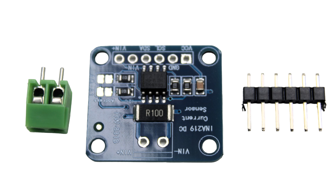
CJMCU-219 INA219 I2C Bi-directional Current/Power Monitoring Module
Need precise digital current measurement at lower currents? The INA219 uses a shunt resistor with I2C output, offering 1% accuracy for loads up to 3.2A — perfect complement to the ACS758 for low-current monitoring.
Measuring AC vs DC Current
DC measurement is straightforward: the output voltage directly represents the instantaneous current. Average multiple ADC readings and convert to current using the sensitivity equation.
AC measurement requires computing the RMS value. For a sinusoidal AC waveform:
- Sample the VIOUT pin at a rate at least 10x the AC frequency (for 50Hz mains, sample at 500 Hz minimum; ideally 10 kHz+).
- Subtract the zero-current offset (VCC/2) from each sample.
- Square each result, sum over one full cycle, divide by number of samples, then take the square root — this is the true RMS.
- Alternatively, use a dedicated RMS-to-DC converter IC (like AD536) or compute it in software using the formula above.
// AC RMS current measurement
float measureACRMS() {
  long sumSquares = 0;
  int samples = 500;
  for (int i = 0; i < samples; i++) {
    int raw = analogRead(CURRENT_PIN);
    float v = raw * (VCC / 1024.0) - ZERO_CURRENT_VOLTAGE;
    float current = v / SENSITIVITY;
    sumSquares += (long)(current * current * 100); // scale to avoid float overflow
    delayMicroseconds(200); // ~5kHz sampling rate
  }
  return sqrt((float)sumSquares / samples / 100.0);
}
For mains AC (230V in India), ensure you have safe wiring practices and proper isolation. The ACS758’s 4.8 kVRMS isolation rating provides excellent protection, but all mains-side wiring must follow electrical safety codes.
High-Current Application Examples
Solar Charge Controller Monitor
Use the ACS758-100B to monitor current flowing from a solar panel array through a PWM or MPPT charge controller to a battery bank. Log current × voltage = power over time using a microcontroller and SD card. Calculate daily energy yield, battery state of charge, and detect reverse leakage current at night.
Electric Bicycle Battery Management
Install an ACS758-50B on the main battery positive rail of an e-bike. Monitor discharge current (motor load), regenerative braking current (negative flow), and charging current. Build a fuel gauge display showing remaining range based on amp-hour integration.
Industrial Motor Current Monitoring
Use the ACS758-200B on a 3-phase motor drive (one sensor per phase). Monitor phase current balance, detect motor overloads, and calculate power factor. Integrate with an ESP32 and MQTT for Industry 4.0 connectivity to a SCADA system.
DC Welding Machine Monitor
Connect the ACS758-200B in series with a DC arc welding machine. Monitor welding current in real time, log weld events, and detect abnormal conditions (arc instability, short circuits). Display on a small TFT for the welder operator.
Safety Considerations
- Wire gauge: Always use appropriately rated cable. At 100A, use minimum 2 AWG (35 mm²) copper cable. At 200A, use 1/0 AWG (50 mm²) or thicker.
- Connector ratings: Ensure all connectors, lugs, and terminals are rated for your maximum current. Undersized connections cause heat, fire risk, and voltage drop.
- Mains AC safety: When measuring mains AC current, use insulated tools, proper enclosures, and follow local electrical codes. The ACS758 itself is isolated, but your wiring is not.
- Fuse protection: Always include an appropriately rated fuse or circuit breaker on the high-current path, upstream of the ACS758.
- Thermal management: At sustained high currents (>100A), the ACS758 package can reach significant temperatures. Ensure adequate airflow and do not exceed the maximum junction temperature rating.
- PCB trace width: If mounting the ACS758 on a PCB, ensure the current-carrying traces are adequately wide. For 50A, traces should be at least 12 mm wide on 1 oz copper, or use a bus bar.
30A Range Current Sensor Module ACS712
For mid-range applications up to 30A, the ACS712 30A module offers the same Hall-effect isolation with convenient module form factor for breadboard and PCB integration.
Frequently Asked Questions
A: Yes, the ACS758 works at VCC = 3.3V. The zero-current output will be 1.65V and sensitivity scales proportionally. However, the ADC resolution is the same 10 bits, so accuracy may be slightly reduced. Use an external ADC (ADS1115) for better precision at 3.3V.
A: The ACS758 power tab package has IP+ and IP- tabs that connect to bus bars or heavy cables using M4 screws. Mount the IC on a PCB or heatsink bracket with the tabs inline with your high-current cable path. Avoid bending the tabs — they are the internal copper conductor.
A: Thermal drift is the most common cause. As the sensor warms up from current-induced heating, the zero offset shifts. Re-calibrate the zero offset after the sensor has reached operating temperature, or implement a temperature-based correction in software.
A: The ACS758-200B can survive peak currents up to 400A for short durations without damage. However, sustained overcurrent causes the copper strap to heat up and eventually fail. Protect with appropriate fuses rated slightly above your maximum expected current.
A: The ACS770 is the next-generation replacement for the ACS758, offering a more compact package, improved accuracy, and better EMC performance. It is largely software-compatible — same sensitivity ranges, same analog output format. The ACS758 is still widely available and fully supported.
Ready to Measure High Currents Safely?
Shop Zbotic’s full range of current sensors, power monitoring modules, and maker electronics — trusted by engineers and students across India.


Add comment