
ESP32 PWM LED dimmer LEDC channel fading is one of the most popular beginner-to-intermediate projects in the Indian electronics community, and for good reason — it demonstrates a critical embedded systems concept while producing immediately satisfying visual results. Unlike the Arduino Uno’s limited analogWrite(), the ESP32’s LEDC (LED Control) peripheral is a dedicated, highly configurable hardware PWM engine that can drive multiple LED channels simultaneously with independent frequencies, resolutions, and duty cycles. This tutorial covers everything from the basic theory to advanced smooth fading algorithms and multi-channel RGB LED control.
ESP32 LEDC Peripheral Overview
The ESP32’s LEDC peripheral was originally designed for LED brightness control but is a fully general-purpose hardware PWM controller. Understanding its architecture is key to using it effectively:
- 16 LEDC channels total — 8 “high-speed” channels (hardware-supported auto-fade) and 8 “low-speed” channels
- 4 independent timers — channels are grouped; each timer can have a different frequency and resolution
- Configurable resolution: 1 to 16 bits (default 8-bit gives 256 steps; 13-bit gives 8192 steps for ultra-smooth fading)
- Frequency range: From 1 Hz to 40 MHz depending on resolution — perfect for both visible LED flicker-free dimming (>1 kHz) and motor/servo control
- Any GPIO can be a LEDC output — unlike Arduino PWM which is restricted to specific pins marked with ~
| Resolution | Steps | Max Frequency | Best Use |
|---|---|---|---|
| 8-bit | 256 | 312 kHz | Simple LED dimming, compatible with analogWrite |
| 10-bit | 1024 | 78 kHz | Smooth dimming for displays |
| 12-bit | 4096 | 19.5 kHz | High-quality audio PWM, precision dimming |
| 13-bit | 8192 | 9.7 kHz | Ultra-smooth fading, imperceptible steps |
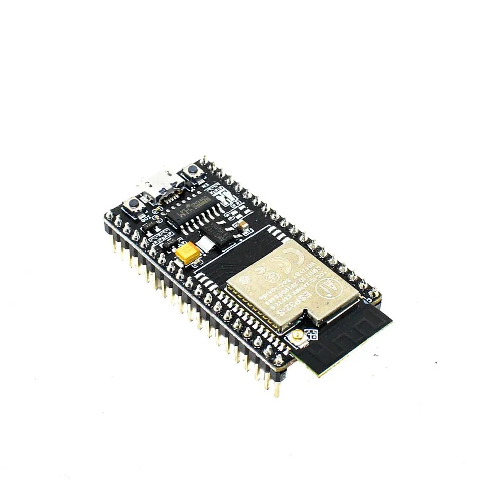
Ai Thinker NodeMCU-32S ESP32 Development Board – IPEX Version
All 16 LEDC PWM channels are available on this NodeMCU-32S board. It is the perfect starting platform for ESP32 LED dimming and PWM experiments, widely available across India.
Basic PWM Setup: ledcSetup and ledcAttachPin
The Arduino ESP32 core provides three key LEDC functions. Note: in ESP32 Arduino core v3.x, the API was updated — we cover both the classic (v2.x) and new (v3.x) API:
Classic API (Arduino ESP32 core v2.x)
const int LED_PIN    = 2;   // GPIO 2 (built-in LED)
const int LEDC_CH    = 0;   // LEDC channel 0 (0-15)
const int FREQ_HZ    = 5000; // PWM frequency: 5 kHz
const int RESOLUTION = 8;   // 8-bit = 0–255

void setup() {
  ledcSetup(LEDC_CH, FREQ_HZ, RESOLUTION); // Configure channel
  ledcAttachPin(LED_PIN, LEDC_CH);         // Attach GPIO to channel
}

void loop() {
  // Fade in
  for (int duty = 0; duty <= 255; duty++) {
    ledcWrite(LEDC_CH, duty);
    delay(10);
  }
  // Fade out
  for (int duty = 255; duty >= 0; duty--) {
    ledcWrite(LEDC_CH, duty);
    delay(10);
  }
}
New API (Arduino ESP32 core v3.x)
In ESP32 Arduino core v3.0+, channels are assigned automatically:
const int LED_PIN    = 2;
const int FREQ_HZ    = 5000;
const int RESOLUTION = 8;

void setup() {
  // New API: attach and configure in one call
  ledcAttach(LED_PIN, FREQ_HZ, RESOLUTION);
}

void loop() {
  for (int duty = 0; duty <= 255; duty++) {
    ledcWrite(LED_PIN, duty); // Pass GPIO, not channel number
    delay(10);
  }
  for (int duty = 255; duty >= 0; duty--) {
    ledcWrite(LED_PIN, duty);
    delay(10);
  }
}
Check your core version: Arduino IDE → Tools → Board → Boards Manager → Search “esp32” by Espressif Systems → see version number.
Smooth LED Fading: Linear vs Gamma-Corrected
A naive linear fade from 0 to 255 does not look smooth to the human eye. The human eye perceives brightness on a logarithmic scale — the difference between 0 and 10 is very visible, but the difference between 245 and 255 is nearly imperceptible. This is why a linear ramp starts fast and then barely seems to change near the top.
The solution is gamma correction, which applies a power curve (gamma ≈ 2.2 for most LED colours) to map linear duty values to perceptually uniform brightness steps:
// Pre-computed gamma correction table for 8-bit (256 entries)
// gamma = 2.2, input 0-255 → output 0-255
const uint8_t gamma8[] = {
    0,  0,  0,  0,  0,  0,  0,  0,  0,  0,  0,  0,  0,  0,  0,  0,
    0,  0,  0,  0,  0,  0,  0,  0,  0,  0,  0,  0,  1,  1,  1,  1,
    1,  1,  1,  1,  1,  1,  1,  1,  1,  2,  2,  2,  2,  2,  2,  2,
    2,  3,  3,  3,  3,  3,  3,  3,  4,  4,  4,  4,  4,  5,  5,  5,
    5,  6,  6,  6,  6,  7,  7,  7,  7,  8,  8,  8,  9,  9,  9, 10,
   10, 10, 11, 11, 11, 12, 12, 13, 13, 13, 14, 14, 15, 15, 16, 16,
   17, 17, 18, 18, 19, 19, 20, 20, 21, 21, 22, 22, 23, 24, 24, 25,
   25, 26, 27, 27, 28, 29, 29, 30, 31, 32, 32, 33, 34, 35, 35, 36,
   37, 38, 39, 39, 40, 41, 42, 43, 44, 45, 46, 47, 48, 49, 50, 50,
   51, 52, 54, 55, 56, 57, 58, 59, 60, 61, 62, 63, 64, 66, 67, 68,
   69, 70, 72, 73, 74, 75, 77, 78, 79, 81, 82, 83, 85, 86, 87, 89,
   90, 92, 93, 95, 96, 98, 99,101,102,104,105,107,109,110,112,114,
  115,117,119,120,122,124,126,127,129,131,133,135,137,138,140,142,
  144,146,148,150,152,154,156,158,160,162,164,167,169,171,173,175,
  177,180,182,184,186,189,191,193,196,198,200,203,205,208,210,213,
  215,218,220,223,225,228,231,233,236,239,241,244,247,249,252,255
};

void loop() {
  // Gamma-corrected fade — looks perfectly smooth!
  for (int i = 0; i <= 255; i++) {
    ledcWrite(LED_PIN, gamma8[i]);
    delay(8);
  }
  for (int i = 255; i >= 0; i--) {
    ledcWrite(LED_PIN, gamma8[i]);
    delay(8);
  }
}
The difference is dramatic — gamma correction makes LED dimming look professional and natural.
Driving Multiple LEDs with Independent LEDC Channels
The ESP32’s 16 LEDC channels are a major advantage over Arduino. You can independently control up to 16 LEDs at different brightness levels simultaneously:
// Classic API example: 4 LEDs on independent channels
#define LED1 13
#define LED2 12
#define LED3 14
#define LED4 27

void setup() {
  // Setup 4 channels: same frequency, 8-bit resolution
  for (int ch = 0; ch < 4; ch++) {
    ledcSetup(ch, 5000, 8);
  }
  ledcAttachPin(LED1, 0);
  ledcAttachPin(LED2, 1);
  ledcAttachPin(LED3, 2);
  ledcAttachPin(LED4, 3);
}

void loop() {
  // Create a flowing "chaser" effect
  for (int i = 0; i <= 255; i++) {
    ledcWrite(0, i);          // LED1 fading in
    ledcWrite(1, 255 - i);    // LED2 fading out
    ledcWrite(2, (i * 2) % 256); // LED3 double speed
    ledcWrite(3, (255 - i * 2 + 256) % 256); // LED4 opposite
    delay(5);
  }
}
Waveshare ESP32-S3 1.47inch 172×320 LCD Display Development Board
Combine ESP32-S3’s 16 LEDC PWM channels with the onboard display to build a professional LED dimmer controller with a real-time brightness readout and colour picker UI.
RGB LED Control: Full Colour Mixing
RGB LEDs have three elements (red, green, blue) that you drive independently to mix any colour. Use 3 LEDC channels for perfect colour control:
#define RED_PIN   25
#define GREEN_PIN 26
#define BLUE_PIN  27

// Classic API: channels 0, 1, 2
void setupRGB() {
  ledcSetup(0, 5000, 8); ledcAttachPin(RED_PIN,   0);
  ledcSetup(1, 5000, 8); ledcAttachPin(GREEN_PIN, 1);
  ledcSetup(2, 5000, 8); ledcAttachPin(BLUE_PIN,  2);
}

void setColor(uint8_t r, uint8_t g, uint8_t b) {
  ledcWrite(0, r);
  ledcWrite(1, g);
  ledcWrite(2, b);
}

// HSV to RGB converter for rainbow cycling
void hsvToRgb(float h, float s, float v,
              uint8_t* r, uint8_t* g, uint8_t* b) {
  int i = int(h * 6);
  float f = h * 6 - i;
  float p = v * (1 - s);
  float q = v * (1 - f * s);
  float t = v * (1 - (1 - f) * s);
  switch (i % 6) {
    case 0: *r=v*255; *g=t*255; *b=p*255; break;
    case 1: *r=q*255; *g=v*255; *b=p*255; break;
    case 2: *r=p*255; *g=v*255; *b=t*255; break;
    case 3: *r=p*255; *g=q*255; *b=v*255; break;
    case 4: *r=t*255; *g=p*255; *b=v*255; break;
    case 5: *r=v*255; *g=p*255; *b=q*255; break;
  }
}

void setup() { setupRGB(); }

void loop() {
  // Rainbow cycle over 5 seconds
  for (int i = 0; i < 360; i++) {
    uint8_t r, g, b;
    hsvToRgb(i / 360.0, 1.0, 1.0, &r, &g, &b);
    setColor(r, g, b);
    delay(14); // 360 * 14ms ≈ 5 seconds
  }
}
PWM LED Dimmer Circuit: MOSFETs for High-Power LEDs
The ESP32’s GPIO can source only 40 mA per pin (120 mA total for all pins). For high-power LEDs (1W, 3W, 10W LED modules used in Indian market LED bulbs and strips), you need a MOSFET driver circuit.
Basic N-Channel MOSFET Dimmer Circuit:
- ESP32 GPIO (3.3V PWM) → Gate of IRLZ44N or IRL520N (logic-level N-MOSFET)
- Add a 100Ω resistor between GPIO and Gate to limit current
- Add a 10kΩ resistor between Gate and GND to pull Gate low when ESP32 boots (prevents random full-power flash)
- Drain → LED negative (cathode) terminal
- Source → GND (shared with ESP32 GND)
- LED positive (anode) → External 12V supply through current-limiting resistor
- Add a flyback diode (1N4007) across the LED in reverse for inductive loads like LED drivers
Important note for Indian 12V LED strips: The popular 5050 RGB LED strips sold in India use 12V. For these, use three N-MOSFET circuits (one per colour channel). The IRLZ44N or the much cheaper IRF520 (available at most Indian component shops) work well for strip currents up to 5A.
For 230V AC LED dimming (mains voltage), never use GPIO-driven MOSFETs directly. Use a commercial TRIAC dimmer module like the RobotDyn AC dimmer module with opto-isolation — safety first for mains-connected projects.
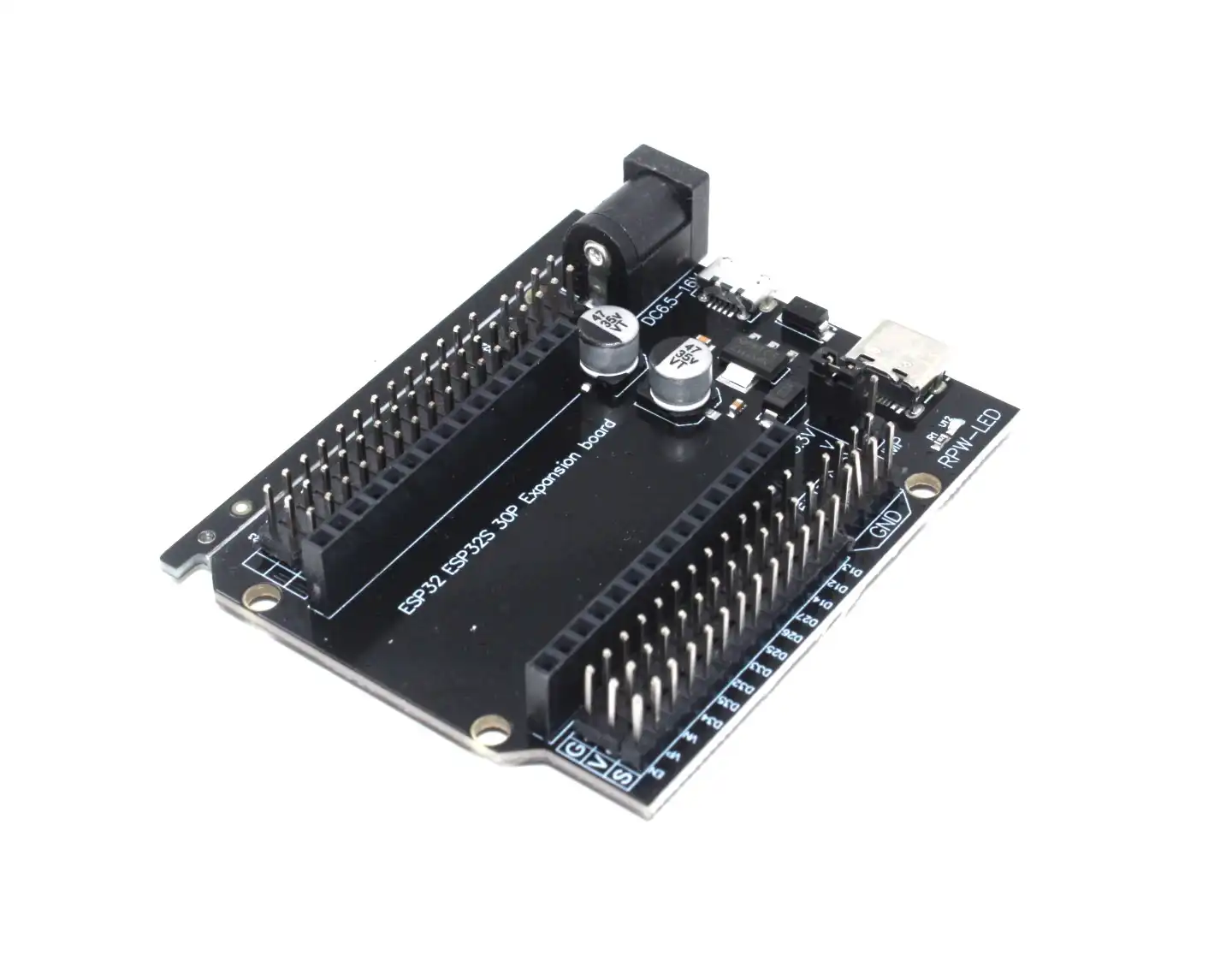
30Pin ESP32 Expansion Board with Type-C and Micro USB
Break out all 30 GPIO pins easily for your multi-channel LEDC PWM LED projects. This expansion board simplifies wiring multiple MOSFET driver circuits for high-power LED dimming.
Advanced Fading Patterns: Breathing, Strobe and Chase
Now that you understand the basics, here are production-ready implementations of popular LED effects:
Breathing / Heartbeat Effect
The breathing effect uses a sine wave for an organic, natural pulsing appearance:
#include <math.h>

void breathingEffect(int ledPin, float period_ms, int iterations) {
  float step = 0;
  unsigned long start = millis();
  while (millis() - start < period_ms * iterations) {
    // Sine wave from 0..1 (output range 5..255 to avoid fully off)
    float brightness = (sin(step) + 1.0) / 2.0;
    uint8_t duty = (uint8_t)(5 + brightness * 250);
    ledcWrite(ledPin, gamma8[duty]); // Apply gamma correction
    step += (2 * M_PI) / (period_ms / 10); // 10ms per step
    delay(10);
  }
}
Strobe Effect
void strobe(int ledPin, int flashes, int onMs, int offMs) {
  for (int i = 0; i < flashes; i++) {
    ledcWrite(ledPin, 255);
    delay(onMs);
    ledcWrite(ledPin, 0);
    delay(offMs);
  }
}
Non-blocking Fading with millis()
For real-world projects that need to fade LEDs while also handling Wi-Fi, sensors, or other tasks, use a non-blocking pattern:
class LEDFader {
public:
  int pin;
  int duty = 0;
  int step = 1;
  int minDuty = 0, maxDuty = 255;
  unsigned long stepInterval = 10;
  unsigned long lastUpdate = 0;

  void begin(int p, int freq = 5000, int res = 8) {
    pin = p;
    ledcSetup(p, freq, res); // Classic API
    ledcAttachPin(p, p % 16);
  }

  void update() {
    if (millis() - lastUpdate >= stepInterval) {
      lastUpdate = millis();
      duty += step;
      if (duty >= maxDuty || duty <= minDuty) step = -step;
      ledcWrite(pin % 16, gamma8[duty]);
    }
  }
};

LEDFader led1, led2, led3;

void setup() {
  led1.begin(13); led1.stepInterval = 8;
  led2.begin(12); led2.stepInterval = 12;
  led3.begin(14); led3.stepInterval = 15;
}

void loop() {
  led1.update();
  led2.update();
  led3.update();
  // Other tasks can run here without blocking the faders
}
Frequently Asked Questions
What is the difference between analogWrite() and ledcWrite() on ESP32?
On Arduino Uno and Mega, analogWrite(pin, value) uses the AVR timer hardware for 8-bit PWM on specific pins. On ESP32, analogWrite() is a compatibility wrapper that internally calls the LEDC functions — it works but limits you to 8-bit and a fixed frequency. Using ledcWrite() directly gives you full control over frequency (1 Hz to 40 MHz), resolution (1–16 bits), and channel assignment. Always use the native LEDC API for professional ESP32 projects.
Why does my LED flicker when dimmed at low brightness?
Visible flicker at low duty cycles usually indicates the PWM frequency is too low. Human eyes can detect flicker below about 50–100 Hz. Increase the LEDC frequency to 1 kHz or higher (5 kHz is the most common recommendation). Note that increasing frequency requires reducing resolution to maintain the clock constraints — at 5 kHz, 8-bit (256 steps) is fine. Also, some cheap LED bulbs have non-linear drivers that flicker more — use high-quality LEDs for smooth dimming.
Can I use LEDC PWM for servo motor control?
Yes! Standard RC servos use a 50 Hz PWM signal with 1–2 ms pulse width. Set LEDC to 50 Hz with 16-bit resolution (65536 steps). Map 0–180 degrees to pulse widths of 1ms–2ms: duty = map(angle, 0, 180, 1638, 3277) for 16-bit at 50 Hz (1ms = 1/20 × 32768 = 1638 steps, 2ms = 3277 steps). The ESP32Servo library automates this for you.
How many LEDC channels can run simultaneously on ESP32?
All 16 channels can run simultaneously. Each high-speed channel (0–7) is linked to one of 4 high-speed timers. Each low-speed channel (8–15) is linked to one of 4 low-speed timers. Channels sharing a timer must use the same frequency and resolution but can have independent duty cycles. For maximum flexibility with different frequencies, assign channels to different timers.
Does ledcFade() work on ESP32 for hardware-assisted fading?
Yes! The ESP32’s high-speed LEDC channels (0–7) support hardware auto-fade via ledcFade(channel, targetDuty, maxFade, time) and ledcFadeWithInterrupt(). Hardware fading runs entirely in the LEDC peripheral with no CPU intervention, freeing your code for other tasks. Only use this with the classic API (v2.x); the v3.x API does not yet expose ledcFade directly — use ledc_set_fade_with_time() from the ESP-IDF driver directly in that case.
Build Your ESP32 LED Projects with Zbotic
Shop ESP32 development boards, expansion shields, and sensor modules for your PWM LED dimmer and IoT projects. Zbotic delivers fast across India — order today and start building tomorrow.


Add comment