
The 555 timer IC is arguably the most popular integrated circuit ever made. Since its introduction by Signetics in 1972, over a billion units are manufactured every year. A single 8-pin DIP package contains a voltage divider, two comparators, an SR flip-flop, an output stage, and a discharge transistor — enough to build oscillators, pulse generators, PWM controllers, delay timers, and much more. This complete guide covers the 555 timer IC pin configuration, all three operating modes with circuit diagrams, design formulas, and practical project ideas you can breadboard today.
What Is the 555 Timer IC?
The NE555 (or simply 555) is a monolithic timing circuit capable of producing accurate time delays or oscillations. The name “555” comes from the three 5 kΩ resistors inside the chip that form an internal voltage divider. It operates from a wide supply range (4.5 V to 15 V for the bipolar NE555, or 2 V to 15 V for the CMOS TLC555/LMC555), and its output can source or sink up to 200 mA — enough to drive LEDs, small relays, and buzzers directly.
The 556 is a dual 555, and the 558 is a quad 555. For battery-powered or low-voltage designs, the CMOS TLC555 is preferred due to its microamp quiescent current and rail-to-rail output swing.
555 Timer Pin Configuration
| Pin | Name | Function |
|---|---|---|
| 1 | GND | Ground (0 V reference) |
| 2 | TRIGGER | Active LOW — when pulled below 1/3 VCC, sets output HIGH and starts timing |
| 3 | OUTPUT | Main output, swings between 0 V and ~VCC − 1.7 V (can source/sink 200 mA) |
| 4 | RESET | Active LOW — pulling LOW forces output LOW regardless of other pins; tie to VCC to disable |
| 5 | CONTROL VOLTAGE | Direct access to 2/3 VCC comparator threshold; decouple with 10 nF cap if unused |
| 6 | THRESHOLD | When voltage exceeds 2/3 VCC, resets flip-flop and pulls output LOW |
| 7 | DISCHARGE | Open collector transistor — pulls LOW when output is LOW (discharges timing capacitor) |
| 8 | VCC | Positive supply voltage (4.5 V to 16 V) |

10CM Female To Female Breadboard Jumper Wires – 40Pcs
Build your 555 timer circuits on a breadboard faster with colour-coded jumper wires — essential for clean, readable prototypes.
Internal Block Diagram and Working
Inside the 555 are:
- Voltage divider: Three equal 5 kΩ resistors divide VCC into thresholds at 1/3 VCC and 2/3 VCC.
- Comparator 1 (Upper): Non-inverting input connected to 2/3 VCC. When THRESHOLD (pin 6) exceeds this, it resets the SR flip-flop (output goes LOW).
- Comparator 2 (Lower): Inverting input at 1/3 VCC. When TRIGGER (pin 2) drops below this, it sets the flip-flop (output goes HIGH).
- SR Flip-Flop: Holds state between trigger events.
- Output Stage: Totem-pole push-pull driver with ~200 mA capability.
- Discharge Transistor: NPN transistor with collector on pin 7 — saturates when output is LOW, discharging the timing cap through RB.
The key insight: the 555 timer is really a voltage comparator that monitors a capacitor charge/discharge cycle relative to 1/3 and 2/3 of the supply. Changing R, C, or the control voltage changes the timing without any software.
Astable Mode: Free-Running Oscillator
In astable (self-triggering) mode, the 555 produces a continuous square wave. There is no stable state — it oscillates indefinitely.
Circuit Connections
- Pin 1 → GND
- Pin 8 → VCC
- Pin 4 → VCC (RESET disabled)
- Pin 5 → 10 nF cap → GND (noise decoupling)
- VCC → RA → pin 7 → RB → pins 2 & 6 (joined) → cap C → GND
- Output on pin 3
Frequency and Duty Cycle Formulas
f = 1.44 / ((RA + 2×RB) × C)
THIGH = 0.693 × (RA + RB) × C
TLOW = 0.693 × RB × C
Duty Cycle = (RA + RB) / (RA + 2×RB) × 100%
Example: 1 kHz Square Wave
Target: f = 1000 Hz, duty cycle ~50%.
Choose C = 100 nF, RB = 7.2 kΩ (use 6.8 kΩ), RA = 1 kΩ.
f = 1.44 / ((1000 + 2×6800) × 100×10-9) = 1.44 / (14600 × 100 nF) ≈ 986 Hz ✓
To achieve 50% duty cycle exactly, make RA very small (or use a bypass diode around RB so THIGH charges through RA + RB but discharges only through RB).

0.1/100nF Multilayer Ceramic Capacitor (Pack of 50)
The 100 nF ceramic cap is the workhorse timing capacitor for 555 astable circuits in the audio and kHz range — and doubles as a decoupling cap on pin 5.
Monostable Mode: One-Shot Timer
In monostable mode, the 555 has one stable state (output LOW). A trigger pulse drives the output HIGH for a precisely calculated time, then returns LOW automatically.
Circuit Connections
- Pin 1 → GND, Pin 8 → VCC, Pin 4 → VCC
- Pin 5 → 10 nF → GND
- VCC → R → pin 6 & 7 (joined) → cap C → GND
- Trigger pulse (active LOW) to pin 2
- Output on pin 3
Pulse Width Formula
T = 1.1 × R × C
Example: 5-Second Delay
T = 5 s. Choose C = 100 µF electrolytic.
R = T / (1.1 × C) = 5 / (1.1 × 100×10-6) = 45.5 kΩ
Use 47 kΩ → T ≈ 5.17 s. Perfect for a door bell hold, relay delay, or LED flasher timer.
Retriggering Note
If a second trigger arrives during the output HIGH period, the standard 555 ignores it (non-retriggerable). If retriggering is needed, use the 74HC123 monostable multivibrator instead.
Bistable Mode: SR Latch
With no timing components (no R-C network), the 555 acts as an SR latch with two stable states. A momentary LOW on pin 2 (TRIGGER) sets output HIGH. A momentary LOW on pin 4 (RESET) forces output LOW.
Application
A bistable 555 makes a perfect debounced switch. Mechanical switches bounce (produce multiple pulses when pressed). Feeding a tactile switch into pin 2 (with pull-up) and another into pin 4 gives a clean, debounced HIGH/LOW toggle — far simpler than a software debounce routine.
PWM Generation with 555
Pulse-width modulation (PWM) from a 555 is achieved in astable mode by making the charge and discharge paths independent:
- Add a diode (1N4148) from pin 7 to the junction of RA and RB, bypassing RB during charging.
- Replace RA with a potentiometer (e.g., 10 kΩ).
- Turning the pot adjusts THIGH independently of TLOW, giving variable duty cycle at nearly constant frequency.
This is commonly used to control LED brightness, small DC motor speed (through a transistor or MOSFET), or servo pulse width.
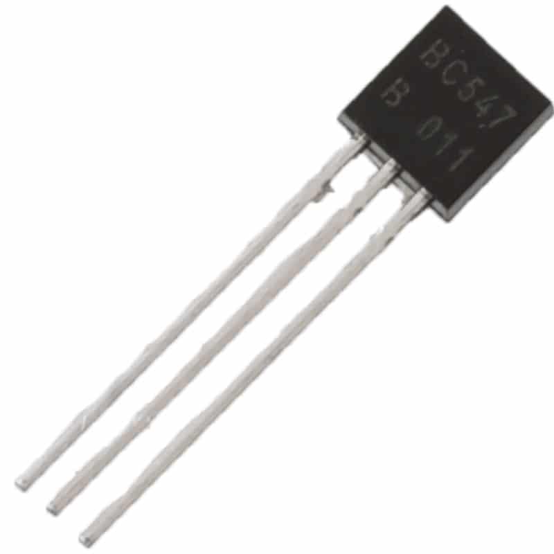
BC547 NPN 100mA Transistor TO-92 (Pack of 10)
Use a BC547 as a buffer between the 555 output and a relay or buzzer — the 555 can drive it directly, protecting the IC from inductive kickback.
Practical Project Ideas
1. Adjustable LED Flasher
Astable mode with a potentiometer for RB. Vary the pot to change flash rate from 0.5 Hz (slow blink) to 10 Hz (fast flicker). Total cost under ₹30.
2. Touch-Sensitive Switch
Monostable 555 with a high-impedance trigger: touching two exposed pads injects enough 50 Hz mains hum to trigger the monostable. LED stays ON for a set time after each touch.
3. Tone Generator / Alarm
Astable at 1–4 kHz driving a small 8 Ω speaker through a 100 µF capacitor. Add a second 555 in astable at 1–2 Hz to amplitude-modulate the first (connect output of slow 555 to pin 4 of fast 555) — creates a siren wail.
4. PWM Fan Controller
Astable 555 at 25 kHz (fan controllers use >20 kHz to avoid audible whine). Duty cycle set by a potentiometer. Output drives a logic-level MOSFET, which drives the fan.
5. Missing Pulse Detector
Monostable with pulse width slightly longer than the expected input period. The output stays HIGH as long as pulses keep retriggering it. A missing pulse means the monostable times out → output goes LOW → alarm fires.
Tips, Tricks and Common Mistakes
- Always decouple pin 5: A 10 nF cap from pin 5 to GND suppresses supply noise on the internal comparator reference — omitting it causes jitter and instability.
- RESET (pin 4) must not float: A floating reset causes random resets. If not used, tie it directly to VCC.
- Minimum trigger pulse width: The trigger pulse must be shorter than the output pulse in monostable mode. If the trigger stays LOW while the timer is running, the output will stay HIGH until the trigger goes HIGH.
- Supply bypass: Place a 100 nF ceramic cap between pin 8 and pin 1 as close to the IC as possible to suppress supply-borne glitches.
- Output current limit: Although rated 200 mA, sustained current heats the chip. For loads above 50 mA, use a transistor or MOSFET buffer.
- Long timing with 555: Avoid electrolytic capacitors above 100 µF due to leakage — timing accuracy degrades. For delays above 1 minute, cascade two monostable stages or use a microcontroller.
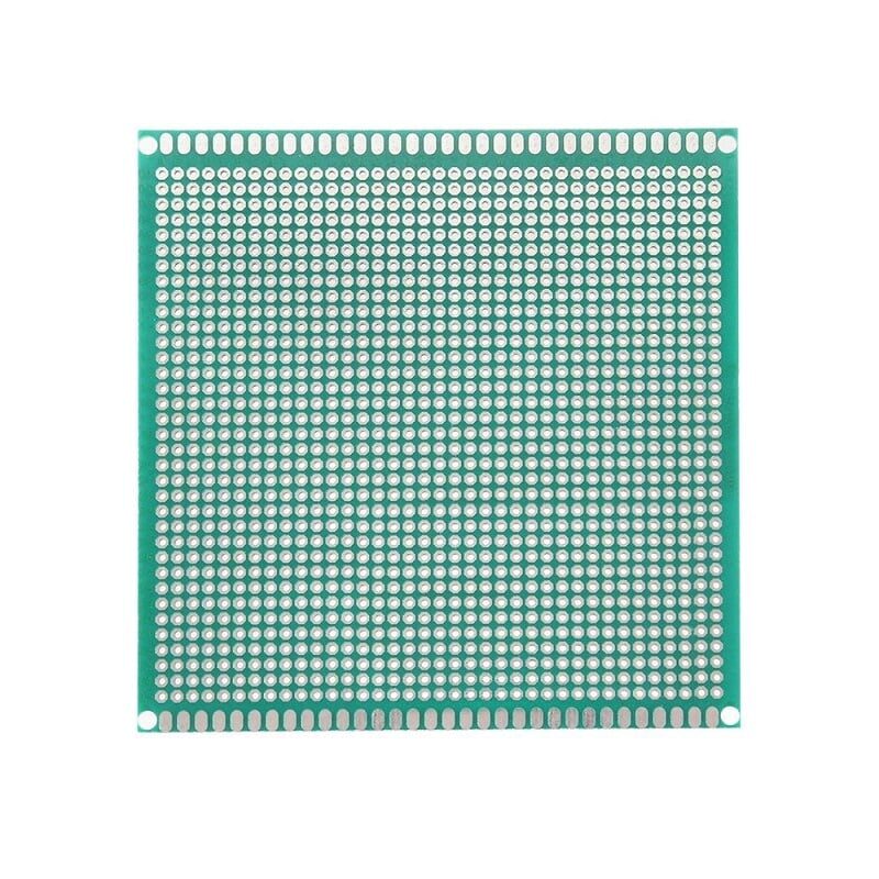
10×10 cm Universal PCB Prototype Board Single-Sided
Graduate from breadboard to a permanent 555 timer circuit — solder your design onto a universal PCB for a robust, long-lasting project build.
Frequently Asked Questions
What voltage does a 555 timer need?
The bipolar NE555 operates from 4.5 V to 16 V. The CMOS TLC555 or LMC555 works from as low as 2 V up to 15 V, making it suitable for 3.3 V and single-cell battery systems.
Can a 555 timer drive a relay directly?
Yes — pin 3 can sink or source up to 200 mA, which is enough to drive a small 5 V relay coil (typically 40–80 mA). Always add a flyback diode (1N4007) across the relay coil to suppress inductive spikes that could damage the 555.
How do I change the frequency of a 555 astable circuit?
Use the formula f = 1.44 / ((RA + 2RB) × C). Increase C or R values to lower frequency; decrease them to raise frequency. Swapping C for a decade lower value (e.g., 10 nF → 1 nF) raises frequency by 10×.
What is the difference between NE555 and LM555?
Functionally identical. NE555 was Signetics’ original part. LM555 is National Semiconductor’s equivalent, now made by Texas Instruments. They are pin-compatible and interchangeable in virtually all circuits.
Why does my 555 oscillate even when I want monostable?
The most common reason is pin 2 floating or picking up noise that keeps retriggering the timer. Add a pull-up resistor (10 kΩ) from pin 2 to VCC, and a 100 nF debounce cap from pin 2 to GND if using a mechanical switch.
Can a 555 timer be used with Arduino?
Yes. The 555 can provide a hardware clock signal, PWM, or debounced button input to Arduino digital pins. Running the 555 from a separate power rail and using a logic-level signal (5 V) keeps them compatible. This offloads timing-critical tasks from the Arduino CPU.
Build Your 555 Timer Circuits Today
Get resistors, capacitors, jumper wires and prototype PCBs from Zbotic — everything you need for your electronics lab, shipped fast across India.


Add comment