
Table of Contents
- Introduction
- PWM Basics for Motor Control
- How PWM Frequency Affects Motor Behaviour
- Audible Noise and the 20 kHz Rule
- Driver Switching Losses
- Motor Inductance and Current Ripple
- Optimal PWM Frequency for Brushed DC Motors
- PWM Frequency for Stepper Motor Drivers
- Arduino PWM Frequencies and How to Change Them
- Practical Frequency Selection Guide
- Frequently Asked Questions
- Conclusion
Introduction
When you call analogWrite(pin, 128) on an Arduino to spin a DC motor at half speed, you are using PWM — Pulse Width Modulation. The duty cycle (in this case 50%) controls effective power delivery. But there is a second parameter that is just as important and far less discussed: PWM frequency.
Most Arduino tutorials never mention PWM frequency — they just use the default ~490 Hz or ~980 Hz and leave it at that. But frequency has a direct impact on motor efficiency, heat generation, audible noise, driver losses, and even motor longevity. Understanding how to select the right PWM frequency for your motor driver separates good motor control designs from mediocre ones.
This guide covers the physics and engineering behind PWM frequency selection, its effects on brushed DC motors and stepper motor drivers, and practical instructions for changing the frequency on Arduino, ESP32, and other common platforms.
PWM Basics for Motor Control
PWM is a technique for controlling the average power delivered to a load by rapidly switching it on and off. Two parameters define a PWM signal:
- Duty Cycle (%): The percentage of time the signal is HIGH. 0% = always off, 100% = always on, 50% = half power.
- Frequency (Hz): How many on-off cycles occur per second. 1000 Hz = 1000 cycles per second = 1 ms per cycle.
For motor control, the duty cycle controls speed (average power), while frequency controls how smooth that power delivery is. At very low frequencies, you can actually see (or hear) the motor pulsing — the motor speeds up and slows down with each PWM cycle. At very high frequencies, the motor’s inductance smooths out the current, and the motor behaves as if it receives a true DC voltage equal to its average.
The mathematical relationship: at duty cycle D (as a fraction) and supply voltage V, the average motor voltage is simply V × D. The motor’s inductance L and the PWM period T determine how much the current actually varies around that average.
How PWM Frequency Affects Motor Behaviour
Here is a summary of the effects across the frequency spectrum:
| Frequency Range | Current Ripple | Audible Noise | Driver Heat | Motor Heating |
|---|---|---|---|---|
| < 100 Hz | Very high | Visible vibration | Low | High (I²R losses) |
| 100 Hz – 1 kHz | High | Loud audible whine | Low | Moderate |
| 1 kHz – 10 kHz | Moderate | Quieter but may still hear | Moderate | Low |
| 10 kHz – 25 kHz | Low | Near silent (above hearing) | Moderate | Very low |
| > 25 kHz | Very low | Silent | High (switching losses) | Very low (core losses rise) |
Audible Noise and the 20 kHz Rule
Human hearing extends from approximately 20 Hz to 20,000 Hz (20 kHz). Any PWM frequency within this range causes the motor — specifically the copper windings and iron core — to vibrate at the switching frequency. This vibration transmits as audible noise.
A motor running on 490 Hz PWM (Arduino default) produces a very noticeable whine at 490 Hz, which sits right in the middle of the most sensitive range of human hearing. It is immediately annoying, especially in close-proximity applications like desktop robots, camera equipment, or household automation.
Raising the PWM frequency above 20 kHz eliminates this audible component. This is why professional motor drives and modern motor driver ICs (like the DRV8871 recommended at 20–100 kHz, or the TMC2208 stepper driver at ~48 kHz) target frequencies above 20 kHz. The motor and wiring still vibrate, but at frequencies you cannot hear.
The sweet spot for most DC motor applications is 20–25 kHz: above audible range, but not so high that driver switching losses dominate.
Driver Switching Losses
Every time a MOSFET in your motor driver switches from on to off (or vice versa), energy is dissipated during the transition. During switching, both drain-source voltage and drain current are non-zero simultaneously — this overlap period dissipates power as heat in the MOSFET.
Switching loss per MOSFET per switch event ≈ ½ × V × I × t_switch, where t_switch is the transition time (typically 50–200 ns for common driver MOSFETs).
Total switching losses increase linearly with PWM frequency: double the frequency, double the switching losses. This is why you cannot simply run at 1 MHz to eliminate all current ripple — the driver would overheat from pure switching losses even with no load.
At the 20 kHz sweet spot, switching losses are typically acceptable for most driver ICs. At 100 kHz, they become significant and must be carefully managed through heatsinking and PCB layout.
Older bipolar H-bridges like the L298N have much higher switching losses than MOSFET-based drivers — another reason to prefer modern MOSFET drivers (DRV8871, TB6612FNG, etc.) at higher switching frequencies.
Motor Inductance and Current Ripple
Motor current ripple (ΔI) — the variation in coil current between the PWM on and off states — is directly related to the motor’s inductance and the PWM frequency:
ΔI = (V × D × (1-D)) / (L × f)
Where: V = supply voltage, D = duty cycle, L = motor inductance, f = PWM frequency.
Key insight: higher frequency = lower current ripple. And lower current ripple means:
- Lower I²R heating in the motor coils (since RMS current is closer to average current)
- Less torque ripple (more consistent rotation at constant speed)
- Less wear on commutator brushes in brushed DC motors
- Better position control accuracy in servos and geared systems
A motor with 10 mH inductance driven from 12V at 50% duty cycle at 490 Hz has a current ripple of: ΔI = (12 × 0.5 × 0.5) / (0.01 × 490) ≈ 0.61A peak-to-peak. At 20 kHz: ΔI = (12 × 0.5 × 0.5) / (0.01 × 20000) ≈ 0.015A — 40× less ripple.
Optimal PWM Frequency for Brushed DC Motors
For common brushed DC motors used with Arduino (12V gear motors, TT motors, small 5V motors):
- Minimum acceptable: 4 kHz (noisy but functional)
- Good compromise: 20–25 kHz (silent, moderate switching losses, acceptable ripple)
- High performance: 50–100 kHz (very low ripple, higher driver heat — only if your driver supports it)
With an L298N driver (bipolar, high switching losses): keep at 4–10 kHz. The L298N datasheet recommends maximum 25 kHz, but practically it heats more at higher frequencies due to its bipolar transistor architecture. In practice, 4–8 kHz is commonly used with L298N in the maker community.
With a MOSFET-based driver (DRV8871, TB6612FNG, BTS7960): 20–50 kHz is ideal and produces minimal additional heat compared to 5 kHz while dramatically improving motor smoothness and reducing noise.

25GA-370 12V 12RPM DC Reducer Gear Motor
A high-torque 12V gear motor that benefits greatly from proper PWM frequency tuning — quieter, smoother, and more efficient when driven at 20+ kHz.
PWM Frequency for Stepper Motor Drivers
Stepper motor drivers like the A4988 and DRV8825 use their own internal PWM (chopper) to control coil current — this is separate from the STEP/DIR signals you send from the microcontroller.
The step pulse frequency (the rate you send STEP pulses) controls stepper speed in steps per second — this is NOT PWM frequency in the conventional sense. However, the internal chopper frequency of the driver IC does matter:
- A4988 chopper frequency: Set by external capacitor on the RC pin, typically ~30–50 kHz
- DRV8825 chopper frequency: Fixed at ~30 kHz internally
- TMC2208/TMC2209: SpreadCycle mode at ~35 kHz chopper; StealthChop mode uses voltage-controlled (not current-controlled) drive for near-silent operation
The practical implication: if your stepper motor whines even at rest or at very low step rates, the whine you hear is the internal chopper frequency. TMC-series drivers with StealthChop mode effectively eliminate this. For CNC and 3D printer builders seeking silent operation, TMC drivers are the upgrade path.
The STEP pulse rate should not exceed the driver’s maximum step frequency — typically 250 kHz for A4988 and DRV8825. For most applications (CNC cutting speed), step rates of 10–100 kHz are typical in microstepping mode.
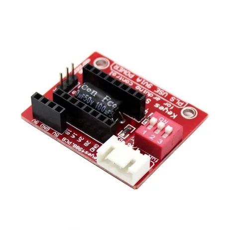
A4988 Stepper Motor Driver (Red)
The A4988’s internal 30–50 kHz chopper frequency provides smooth current control for NEMA 17 stepper motors in 3D printers and CNC machines.
Arduino PWM Frequencies and How to Change Them
Arduino Uno (ATmega328P) default PWM frequencies depend on which pin:
- Pins 3, 11 (Timer 2): 490 Hz default
- Pins 5, 6 (Timer 0): 980 Hz default (Timer 0 also controls millis/delay — change with caution)
- Pins 9, 10 (Timer 1): 490 Hz default
Changing PWM Frequency on Arduino Uno
PWM frequency is controlled by the timer prescaler register. For Timer 1 (pins 9, 10), changing the prescaler to 1 raises frequency to 31.4 kHz:
// Change Timer 1 (pins 9, 10) to ~31.4 kHz PWM
// Add to setup() before any analogWrite calls
void setPWMFrequency_31kHz_pins9_10() {
  // Clear prescaler bits and set prescaler to 1 (no division)
  TCCR1B = (TCCR1B & 0b11111000) | 0x01;
}

// Other options for Timer 1:
// 0x01 → 31372.55 Hz (~31.4 kHz)
// 0x02 → 3921.16 Hz  (~4 kHz)
// 0x03 → 490.20 Hz   (default, ~490 Hz)
// 0x04 → 122.55 Hz
// 0x05 → 30.64 Hz
Warning: Do not change Timer 0 prescaler — it breaks millis(), micros(), and delay(). Use Timer 1 or Timer 2 for motor PWM instead.
PWM Frequency on ESP32
ESP32’s LEDC (LED control) peripheral makes frequency setting trivial:
// ESP32: set PWM at 20 kHz, 8-bit resolution
const int motorPin = 16;
const int channel = 0;
const int freq = 20000;   // 20 kHz
const int resolution = 8; // 8-bit (0-255)

ledcSetup(channel, freq, resolution);
ledcAttachPin(motorPin, channel);
ledcWrite(channel, 128); // 50% duty cycle
ESP32 allows any frequency from 1 Hz to several MHz — simply change the freq parameter. 20 kHz is recommended for most DC motor applications.
Practical Frequency Selection Guide
Scenario 1: Small robot with L298N + TT motors (5V)
Recommended frequency: 4–8 kHz. The L298N has high switching losses; going above 10 kHz makes it run hotter without meaningful improvement. Default Arduino ~490 Hz causes audible whine — change Timer 1 prescaler to 0x02 for ~3.9 kHz (much quieter, minimal extra heat).
Scenario 2: Desktop camera slider with DRV8871 + 12V gear motor
Recommended frequency: 20–25 kHz. Silent operation is critical for camera work. The DRV8871 handles this efficiently. Use ESP32 LEDC at exactly 20 kHz or Arduino Timer 1 prescaler 0x01 (~31 kHz).
Scenario 3: 3D printer with A4988 + NEMA 17
The A4988’s internal chopper is fixed at ~30–50 kHz — you do not control it. Focus on step pulse rate (set by firmware like Marlin). Minimum steps/second for smooth motion depends on microstepping — at 1/16 microstepping, you need 200 × 16 = 3200 steps/rev; for 300 mm/min travel on a 2mm/rev leadscrew: 300/2 × 3200/60 = 8000 steps/s. This is well within driver capability.
Scenario 4: Heavy robot with BTS7960 IBT-2 + 12V gear motors
Recommended frequency: 10–25 kHz. The BTS7960 MOSFET driver handles high frequencies well. Match frequency to the motor’s inductance — motors with higher inductance (larger wound motors) benefit more from higher frequency for ripple reduction.

Ebike 500W 24V DC Motor MY1020
High-power 24V DC motor for go-karts and e-bikes — optimal PWM frequency (10–20 kHz) is critical at this power level to minimise driver heating and motor losses.
Frequently Asked Questions
Q: My motor hums and vibrates even at 100% duty cycle. Is that the PWM frequency?
At 100% duty cycle, no switching occurs — the motor should not whine from PWM. The noise you hear at 100% duty cycle is likely mechanical vibration from the motor’s load, bearing noise, or gear mesh frequency. PWM-related noise only occurs when the duty cycle is between 0% and 100%.
Q: Does higher PWM frequency use more battery power?
A small amount more — due to increased driver switching losses. At reasonable frequencies (20 kHz) with modern MOSFET drivers, the difference is less than 2–5% compared to 1 kHz. The motor itself may actually be more efficient at higher frequency due to lower I²R losses from reduced current ripple.
Q: Can I use PWM directly on an Arduino pin to run a motor without a driver?
No. Arduino I/O pins are rated at 40mA maximum. Even the smallest motors draw 100–500mA. You will damage the Arduino’s ATmega chip. Always use a motor driver IC between the Arduino and the motor, regardless of motor size or voltage.
Q: What PWM frequency does the L298N module work best at?
The L298N works with PWM up to ~25 kHz but gets noticeably warmer above 10 kHz due to bipolar transistor switching losses. For a good balance of quieter operation and reasonable driver temperature, use 4–8 kHz with L298N. This is quieter than the default Arduino 490 Hz while keeping the driver at reasonable temperatures.
Q: How does PWM frequency relate to motor speed accuracy?
In open-loop control, PWM frequency does not directly affect speed accuracy. However, higher frequency means smaller current ripple which means smoother torque, which means less velocity variation at constant PWM — especially at low duty cycles near the motor’s minimum start-up threshold. For closed-loop speed control with encoders, higher PWM frequency allows tighter PID tuning with higher gain stability margins.
Q: At what PWM duty cycle is a motor most efficiently controlled?
From a motor efficiency perspective, running at higher duty cycles (closer to 100%) at full rated voltage is most efficient because proportionally less time is spent in the switching transition states. For speed reduction, consider using a lower supply voltage (via a buck converter) and running at high duty cycle rather than a high supply voltage at low duty cycle — this can be more efficient in some applications.
Conclusion
PWM frequency is an underappreciated but genuinely important parameter in motor control system design. The key principles: low frequencies (below 1 kHz) cause audible noise and high current ripple; frequencies above 20 kHz eliminate audible noise and dramatically reduce current ripple; very high frequencies (above 50 kHz) increase driver switching losses and require careful thermal management.
For most Arduino + brushed DC motor projects with MOSFET drivers, 20–25 kHz is the optimal frequency: silent, low ripple, and well within driver capabilities. For L298N-based projects, 4–8 kHz is the practical sweet spot. Always confirm your driver IC’s maximum PWM frequency from its datasheet before setting a high frequency.
Small changes in PWM frequency can make the difference between an annoyingly noisy robot and a smooth, professional-feeling machine. It takes five minutes to change a timer prescaler — the improvement in operation quality is well worth the effort.
Find the Right Motor & Driver on Zbotic
From efficient MOSFET-based motor drivers to high-torque gear motors, Zbotic has everything for your next motor control project. Shipped across India with fast delivery.


Add comment