
Understanding capacitor types — ceramic, electrolytic, and tantalum — is one of the most essential skills for any electronics hobbyist or engineer in India. Whether you are building an Arduino project, designing a power supply, or prototyping on a breadboard, picking the wrong capacitor can cause your circuit to malfunction, overheat, or even fail permanently. This comprehensive guide breaks down every major capacitor type, explains their specifications in plain language, and helps you choose the right one every time.
Table of Contents
- What Is a Capacitor and How Does It Work?
- Ceramic Capacitors: Workhorse of the Electronics World
- Electrolytic Capacitors: High Capacitance, Polarity Matters
- Tantalum Capacitors: Compact, Stable, and Expensive
- Film Capacitors and Other Types
- Capacitor Comparison Table
- How to Choose the Right Capacitor for Your Project
- Frequently Asked Questions
What Is a Capacitor and How Does It Work?
A capacitor is a passive electronic component that stores electrical energy in an electric field between two conductive plates separated by a dielectric (insulating) material. The capacitance — measured in Farads (F) — determines how much charge the capacitor can store at a given voltage.
In practical circuits, capacitors serve several key roles:
- Decoupling / Bypass: Filtering out noise from power supply lines to keep ICs stable.
- Energy storage: Providing bursts of current in camera flashes, motor starters, etc.
- Timing circuits: Working with resistors in RC circuits to set delay timers (555 timer circuits).
- AC coupling / Signal blocking: Passing AC signals while blocking DC bias.
- Power factor correction: Used in AC power systems to improve efficiency.
Capacitance values in hobbyist electronics range from 1 pF (picofarad) up to 47,000 µF (microfarad). The dielectric material and construction method determine which application a capacitor is suited for.

0.1µF Ceramic Capacitor (Pack of 50)
The classic 100nF / 104 ceramic capacitor — a must-have decoupling cap for every Arduino and microcontroller project. Pack of 50 for breadboard prototyping.
Ceramic Capacitors: Workhorse of the Electronics World
Ceramic capacitors are the most commonly used capacitor type in modern electronics. They use ceramic material (typically barium titanate) as the dielectric, and are available in tiny SMD (surface-mount) packages like 0402 and 0603, as well as through-hole disc shapes for breadboard use.
Key Characteristics of Ceramic Capacitors
- Capacitance range: 1 pF to 100 µF (most common: 1 nF to 100 nF)
- Voltage rating: 10V to 1000V+
- Polarity: Non-polarised — can be inserted in any direction
- Temperature stability: Depends on dielectric class (C0G/NP0 = best; X7R = good; Y5V = poor)
- ESR (Equivalent Series Resistance): Very low — excellent for high-frequency bypass
- Physical size: Very small, especially SMD variants
Ceramic Capacitor Classes: C0G vs X7R vs Y5V
This is where beginners often get confused. The EIA temperature code tells you how stable the capacitance is across temperature and voltage:
| Class | Temp Range | Capacitance Drift | Best For |
|---|---|---|---|
| C0G / NP0 | -55°C to +125°C | ±30 ppm/°C | Timing, RF, precision |
| X7R | -55°C to +125°C | ±15% | Decoupling, general use |
| Y5V | -30°C to +85°C | +22%/-82% | Non-critical filtering only |
For Arduino and Raspberry Pi decoupling, X7R 100nF caps placed directly across power pins (VCC and GND) are the standard recommendation. Always use one per IC.
Best Use Cases for Ceramic Capacitors
- Bypass/decoupling capacitors near IC power pins (100nF standard)
- High-frequency filter circuits (RF, oscillators)
- Timing capacitors in 555 timer and RC circuits
- Input/output filtering on DC-DC converters
- Snubber circuits for relay switching

0.1/100nF Multilayer Ceramic Capacitor (Pack of 50)
Through-hole multilayer ceramic capacitor, ideal for noise suppression on microcontroller boards. Pack of 50 — great value for prototyping.
Electrolytic Capacitors: High Capacitance, Polarity Matters
Electrolytic capacitors use an electrolyte (liquid or solid salt) as the dielectric, enabling very high capacitance values in a physically compact package. They are the go-to choice whenever you need capacitance values above a few microfarads — for example, in power supply filters, audio amplifiers, and motor driver circuits.
Key Characteristics of Electrolytic Capacitors
- Capacitance range: 1 µF to 100,000 µF (and beyond in supercapacitors)
- Voltage rating: 6.3V to 450V (always choose a rating 20–50% above your circuit voltage)
- Polarity: POLARISED — the positive lead (longer, or marked +) must connect to the higher voltage point
- ESR: Higher than ceramic capacitors, especially at high frequencies
- Temperature: Performance degrades significantly above 85°C; look for 105°C-rated caps for power supplies
- Lifespan: Limited (typically 2,000–5,000 hours at rated temperature) — a common failure point in old electronics
Aluminium Electrolytic vs Solid Electrolytic
Traditional aluminium electrolytic capacitors use liquid electrolyte and are cheap but have higher ESR and limited lifespan. Solid aluminium and solid polymer electrolytics offer lower ESR, longer life, and better high-frequency performance — used in modern motherboards and switching power supplies.
Critical Warning: Never Reverse-Bias an Electrolytic!
Connecting an electrolytic capacitor with reversed polarity can cause it to heat up, bulge, and potentially explode violently. Always double-check the polarity marking — the negative terminal is marked with a white or grey stripe with minus signs on the capacitor body. The positive lead is always the longer leg in a new through-hole capacitor.
Best Use Cases for Electrolytic Capacitors
- Power supply bulk capacitors (filtering rectified AC to DC)
- Decoupling at the power supply input of a PCB (typically 10 µF to 1000 µF)
- Audio coupling and tone control circuits
- Motor driver input filter
- Energy buffer in LED drivers and battery chargers
Tantalum Capacitors: Compact, Stable, and Expensive
Tantalum capacitors use tantalum pentoxide as the dielectric. They offer higher capacitance density than electrolytic caps (meaning more capacitance per cubic millimetre), excellent frequency characteristics, and very long shelf life. However, they are significantly more expensive and have a critical failure mode — short-circuit failure if voltage ratings are exceeded.
Key Characteristics of Tantalum Capacitors
- Capacitance range: 0.1 µF to 2200 µF
- Voltage rating: 2V to 50V (always derate to 50–60% of rated voltage in circuits)
- Polarity: Polarised — the positive terminal is clearly marked with a stripe or + symbol
- ESR: Low — better than aluminium electrolytic
- Temperature stability: Excellent over -55°C to +125°C
- Package: Usually SMD (surface-mount) in sizes 0402 to size D/E
Tantalum vs Electrolytic: When to Use Which?
Use tantalum when board space is at a premium (portable devices, wearables), when you need better frequency response than electrolytic, or when long-term reliability matters. Use electrolytic when cost is the priority, high voltage operation is needed, or large capacitance values (above a few hundred µF) are required.
Tantalum failure warning: Tantalum caps fail short-circuit (unlike ceramics that fail open). If a tantalum is stressed beyond its voltage rating, it can catch fire. Always derate by at least 50%: for a 5V supply, use a 10V-rated tantalum cap.
Film Capacitors and Other Types
Film capacitors use a thin plastic film (polyester, polypropylene, polycarbonate) as the dielectric. They are non-polarised, very stable, and have low ESR — but are physically large relative to their capacitance. Common uses include:
- AC motor run/start capacitors
- Audio crossover networks (audiophile grade)
- High-voltage snubber circuits
- Timing circuits requiring stable capacitance
Supercapacitors (EDLC)
Supercapacitors (also called ultracapacitors or EDLC — Electric Double Layer Capacitors) store charge electrostatically at the electrolyte–electrode interface rather than in a dielectric. They can store 1–3000 Farads at low voltages (typically 2.7V to 5V per cell). They bridge the gap between conventional capacitors and batteries, used in energy harvesting, backup power for RTC (real-time clock) circuits, and regenerative braking systems.
Capacitor Comparison Table
| Property | Ceramic | Electrolytic | Tantalum | Film |
|---|---|---|---|---|
| Capacitance Range | 1pF–100µF | 1µF–100,000µF | 0.1µF–2200µF | 1nF–100µF |
| Polarity | No | Yes | Yes | No |
| Max Voltage | Up to 1kV+ | Up to 450V | Up to 50V | Up to 1kV+ |
| ESR | Very Low | High | Low | Very Low |
| Cost | Very Low | Low | High | Medium |
| Size | Very Small | Medium-Large | Small | Large |
| Lifespan | Very Long | Limited | Very Long | Very Long |
| Failure Mode | Open | Open/Bulge | Short (fire risk) | Open |
How to Choose the Right Capacitor for Your Project
Here is a quick decision framework for Indian makers and hobbyists building on Arduino, ESP32, or custom PCBs:
- Decoupling near ICs: Use 100nF X7R ceramic cap, one per IC, placed as close to the VCC–GND pins as possible.
- Bulk power filtering (>10µF): Use aluminium electrolytic. Pick a voltage rating 1.5× to 2× your supply voltage.
- Timing circuits (555, RC filters): Use C0G/NP0 ceramic for stable, temperature-independent timing.
- High-frequency filtering/DC-DC converters: Use ceramic or tantalum for low ESR.
- Audio signal coupling: Film capacitors (polyester) for best sound quality; electrolytic acceptable for non-critical paths.
- Compact, high-density designs: Tantalum (SMD), but always derate voltage to 50%.
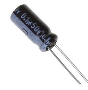
0.1µF 50V Capacitor (Pack of 50)
High-voltage 50V rated 100nF capacitors — ideal for circuits with 24V or 36V power rails where standard 10V or 16V caps would be insufficient.
Reading Capacitor Values: Decoding the Markings
Ceramic capacitors use a 3-digit code: the first two digits are the value, the third is the multiplier (number of zeros to add), in picofarads. So:
- 104 = 10 × 10,000 = 100,000 pF = 100 nF = 0.1 µF
- 102 = 10 × 100 = 1,000 pF = 1 nF
- 473 = 47 × 1,000 = 47,000 pF = 47 nF
Electrolytic capacitors are usually printed directly (e.g., 1000µF 25V). Tantalums are printed with a code or directly as well.

LCR-T4 Transistor & Capacitance ESR Meter
Auto-identifies capacitors, transistors, resistors, diodes, and MOSFETs. Measures capacitance and ESR — perfect for testing capacitors from your component bin.
Practical Prototyping Tips for Indian Hobbyists
- Always keep a stock of 100nF ceramic caps — you will use them in virtually every project.
- Store electrolytic capacitors with their leads through a foam strip to prevent bending and short-circuits.
- For the hot and humid Indian climate, prefer 105°C-rated electrolytic caps over 85°C-rated ones for longer life.
- Use breadboard jumper wires to quickly prototype RC filter circuits before committing to a PCB.
- When testing an unknown capacitor from a scrap board, use the LCR meter to measure its actual capacitance and ESR — old electrolytics often have 50% reduced capacitance.

10CM Female To Female Breadboard Jumper Wires — 40Pcs
Essential for breadboard prototyping of capacitor filter and timing circuits. Standard 2.54mm pitch, 40 wires per pack.
Frequently Asked Questions
Can I replace an electrolytic capacitor with a ceramic capacitor?
Only if the required capacitance value is within the ceramic cap’s range (generally up to 10–22 µF) and the ceramic cap’s voltage rating meets or exceeds the circuit requirement. For values above 22 µF, electrolytic is typically the only practical through-hole option. Also note that ceramic capacitors have no polarity restriction, which simplifies installation.
What happens if I exceed a capacitor’s voltage rating?
Exceeding the voltage rating breaks down the dielectric — permanently damaging ceramic and film caps, causing bulging or explosion in electrolytics, and potential fire in tantalums. Always choose a capacitor with a voltage rating at least 20–50% higher than the maximum voltage in your circuit.
Why does my 1µF ceramic capacitor measure only 0.2µF on my LCR meter?
Y5V and X7R ceramic caps exhibit significant capacitance drop under DC bias (DC bias effect). A 1µF X7R cap at its rated voltage may only have 20–50% of its nominal capacitance. This is why it is important to choose capacitors with appropriate voltage derating, or switch to C0G/NP0 for critical timing applications.
Which capacitor is best for Arduino decoupling?
A 100nF (0.1µF) ceramic capacitor placed as close as possible to the VCC and GND pins of the Arduino’s microcontroller (ATmega328P) is the standard recommendation. Add a 10µF electrolytic capacitor at the power input for bulk decoupling. This two-stage filter handles both high-frequency and low-frequency supply noise.
How do I store capacitors to prevent damage?
Keep capacitors in anti-static bags or original tape reels, away from humidity and heat. For long-term storage of electrolytic capacitors (more than a year), periodically apply a low voltage (below the rated voltage) for a few hours to reform the oxide layer — this prevents increased leakage current when the cap is eventually used.
Conclusion: Build Your Capacitor Knowledge Alongside Your Component Stock
Capacitors are humble components, but choosing the wrong type can ruin an otherwise well-designed circuit. The golden rules: use ceramic for decoupling and high-frequency, electrolytic for bulk energy storage, tantalum when space is tight and you can afford the higher price. Keep a generous stock of 100nF ceramic caps — you will reach for them on every project. And pick up an LCR meter to verify your capacitors before trusting them in a critical circuit. Happy building!


Add comment