
If you have ever built a power supply or a DC-DC converter and measured more ripple voltage than your calculations predicted, the culprit is almost certainly capacitor ESR. Equivalent Series Resistance — the hidden resistance inside every capacitor — is one of the most important yet least discussed parameters in practical electronics. Understanding capacitor ESR explained in plain terms can be the difference between a rock-solid power supply and one that overheats, oscillates, or delivers noisy voltage to your sensitive microcontrollers and sensors.
This guide breaks down what ESR actually is, where it comes from, why it matters critically in power circuits, how to measure it, and how to select low-ESR capacitors for your projects. Whether you are designing a voltage regulator, a motor driver, or a switch-mode power supply, this is the knowledge that will immediately improve your results.
Table of Contents
- What Is ESR? The Ideal vs Real Capacitor
- Where Does ESR Come From?
- How ESR Affects Your Power Circuits
- ESR and Output Ripple: The Maths
- ESR and Heat: Why Capacitors Fail
- How to Measure ESR
- ESR by Capacitor Type
- Choosing Low-ESR Capacitors for Power Circuits
- Paralleling Capacitors to Reduce Effective ESR
- Frequently Asked Questions
What Is ESR? The Ideal vs Real Capacitor
An ideal capacitor is a pure reactive element — it stores charge, passes AC signals based on frequency, and has zero resistance. Real capacitors, however, have several non-ideal parasitic elements that engineers model with an equivalent circuit:
- ESR (Equivalent Series Resistance) — resistance in series with the capacitance, from lead resistance, electrolyte resistance, foil resistance, and contact resistance
- ESL (Equivalent Series Inductance) — parasitic inductance from the lead wires and internal foil windings
- Leakage resistance — very high value resistance in parallel, representing DC leakage through the dielectric
Of these, ESR is the most practically significant in power electronics. It is measured in milliohms (mΩ) for high-quality capacitors to tens of ohms for worn-out or poor-quality electrolytics. The lower the ESR, the more closely the capacitor behaves like the ideal component you assumed in your calculations.
Where Does ESR Come From?
ESR is not a single source of resistance — it is the sum of several contributing resistances within the capacitor:
Electrolyte Resistance (Dominant in Aluminium Electrolytics)
In aluminium electrolytic capacitors, a liquid electrolyte acts as the effective negative plate of the capacitor. This liquid has significant ionic resistance, which makes up the bulk of ESR in standard electrolytics. As the capacitor ages, electrolyte dries out and its resistance increases — this is why old capacitors have higher ESR than new ones.
Foil and Lead Resistance
The aluminium or tantalum foils inside the capacitor have finite resistance. The longer and thinner the foil, the higher its contribution to ESR. This is why larger-capacity capacitors often have lower ESR — the larger foil area reduces resistance.
Contact and Terminal Resistance
The connections between the internal foil and the external terminals contribute a small but measurable resistance, especially if corrosion is present.
Dielectric Loss (Dominant in Ceramic Capacitors)
In ceramic capacitors, ESR is primarily due to dielectric losses — energy lost as heat as the electric field alternates within the ceramic material. This is why ceramic capacitor ESR is specified with a dissipation factor (DF or tan δ) rather than a direct resistance value.
How ESR Affects Your Power Circuits
ESR has consequences at two levels: the output voltage and the capacitor’s own temperature.
Output Ripple Voltage
In a DC power supply or DC-DC converter, the output capacitor is supposed to smooth the pulsating current from the rectifier or switching transistor into a steady DC voltage. But when current pulses flow through the ESR, they create a proportional voltage drop: V = I × ESR. This voltage drop adds directly to the output ripple — and it appears at the switching frequency, which is often the dominant ripple component in modern switch-mode supplies.
Stability of Voltage Regulators
Many linear voltage regulators (including the popular LDO types) depend on a specific output capacitor ESR range for stability. Too low an ESR can cause oscillation; too high can cause sluggish transient response. This is a common and baffling failure mode when switching capacitor types without checking the datasheet: replace an electrolytic output capacitor with a ceramic one, and the regulator starts oscillating even though the capacitance value is correct.
Transient Response
When a digital circuit switches (e.g., an MCU waking up from sleep, a motor starting), it draws a sudden burst of current. The capacitor on the supply rail must supply this instantly. High ESR means the voltage sags proportionally to the surge current — this sag can cause brown-out resets in microcontrollers and corrupt I2C or SPI transactions.

0.1/100nF – TH Multilayer Ceramic Capacitor (Pack of 50)
Multilayer ceramic capacitors have extremely low ESR — ideal as decoupling caps right at IC power pins. Essential for stable, low-noise power in any digital circuit.
ESR and Output Ripple: The Maths
Understanding the contribution of ESR to output ripple helps you make better component choices. The total output ripple of a switch-mode power supply has two components:
1. Capacitive ripple: Vcap = ΔI / (8 × f × C) — where ΔI is the inductor ripple current, f is switching frequency, and C is capacitance.
2. ESR ripple: VESR = ΔI × ESR
Total ripple ≈ Vcap + VESR
In practice, for a 100kHz buck converter with 1A ripple current and a capacitor with 100mΩ ESR, the ESR contribution alone is 100mV peak-to-peak — which often dominates over the capacitive ripple. Reducing ESR from 100mΩ to 10mΩ reduces this ripple contribution by 10× without changing capacitance at all.
This is exactly why capacitor datasheets specify ESR, and why you should always check it — not just the capacitance and voltage rating.
ESR and Heat: Why Capacitors Fail
Power dissipated in ESR generates heat inside the capacitor: P = I² × ESR. In a switch-mode power supply, ripple currents can be surprisingly large (often 1–3A in a 5A output supply). With a capacitor ESR of 100mΩ and 2A ripple current: P = (2)² × 0.1 = 0.4W dissipated inside the capacitor.
Electrolytic capacitors are particularly vulnerable because the heat accelerates electrolyte evaporation. The hotter the capacitor runs, the faster the electrolyte dries, which increases ESR, which generates more heat — a thermal runaway cycle. This is why capacitors are often the first component to fail in power supplies that run hot.
The practical rule: keep your output capacitor away from heat sources and ensure adequate airflow. In PCB design, do not place output capacitors directly next to inductors, transformers, or power transistors.
How to Measure ESR
Standard digital multimeters cannot measure ESR directly — they use DC for resistance measurement, but ESR is an AC parameter (typically measured at 100kHz). To measure ESR, you need:
Dedicated ESR Meter
The most convenient option. ESR meters like the LCR-T4 and dedicated ESR-specific tools inject a small AC signal into the capacitor and measure the resulting voltage, computing ESR from Ohm’s law. Some can measure in-circuit (without desoldering the capacitor), which is invaluable for diagnosing failing capacitors in old equipment.
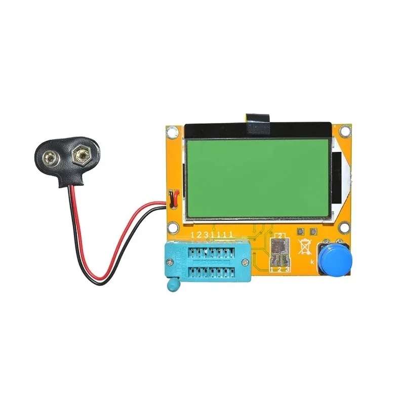
LCR-T4 12864 LCD Transistor Tester – Resistance, Capacitance, ESR & SCR Meter
This versatile LCR-T4 tester measures ESR directly alongside capacitance, resistance, and transistor parameters. An essential bench tool for diagnosing failing capacitors and verifying new ones before use.
LCR Meter
A bench LCR meter measures inductance (L), capacitance (C), and resistance (R) at user-selectable frequencies. Better ones measure at 100kHz which is the standard frequency for ESR specification of electrolytic capacitors. LCR meters are more expensive but more accurate and flexible than dedicated ESR meters.
Oscilloscope Method
With a function generator and oscilloscope, you can inject a known AC current into the capacitor and measure the voltage drop to compute ESR. This method is suitable for low-ESR capacitors where dedicated ESR meters struggle to measure accurately in the milliohm range.
ESR by Capacitor Type
Different capacitor technologies have vastly different ESR characteristics:
| Capacitor Type | Typical ESR Range | Best Use Case |
|---|---|---|
| Aluminium electrolytic (standard) | 100mΩ – 10Ω | Low-frequency bulk filtering (50/60Hz rectifiers) |
| Aluminium electrolytic (low-ESR) | 10mΩ – 100mΩ | SMPS output, audio circuits |
| Solid polymer electrolytic | 5mΩ – 30mΩ | High-frequency SMPS, CPU VRM |
| Tantalum | 50mΩ – 200mΩ | Space-constrained filtering, stable ESR over temperature |
| Multilayer ceramic (X5R/X7R) | 1mΩ – 10mΩ | High-frequency decoupling, RF bypass |
| Film capacitor (polypropylene) | 1mΩ – 5mΩ | Precision audio, high-frequency filtering |
The key takeaway: ceramic capacitors have the lowest ESR, making them ideal for high-frequency decoupling. Electrolytic capacitors have higher capacitance in smaller packages, making them better for bulk energy storage — but choose low-ESR types for any power supply application.
Choosing Low-ESR Capacitors for Power Circuits
When selecting capacitors for power supply output stages, follow these guidelines:
- Always check the ESR in the datasheet, not just the capacitance value. ESR is usually specified at 100kHz at 20°C. Look for the impedance vs frequency curve (often called a Bode plot) — it shows how ESR changes with frequency.
- Match ESR to the regulator’s requirements. Some LDO regulators explicitly specify a minimum and maximum ESR for the output capacitor. This is not optional — check the regulator IC’s application note.
- Use low-ESR electrolytic series (e.g., Nichicon HE, Panasonic FR, Rubycon ZL) for SMPS output capacitors. These use special electrolytes and low-resistance foil to achieve 5–20× lower ESR than standard grades.
- For high-frequency applications (>100kHz), use solid polymer capacitors or ceramics rather than electrolytic. At very high frequencies, ESL dominates and capacitors start looking inductive.
- Consider temperature. Electrolytic ESR increases dramatically at low temperatures. A capacitor rated 100mΩ at 25°C might have 500mΩ at −10°C — a concern for outdoor electronics in North Indian winters.

0.1µF Ceramic Capacitor (Pack of 50)
With ESR in the single-digit milliohm range, this 100nF ceramic cap is the go-to decoupling capacitor for all digital ICs. Its low ESR ensures clean power delivery right where your IC needs it most.
Paralleling Capacitors to Reduce Effective ESR
When you cannot find a single capacitor with low enough ESR, paralleling multiple capacitors is a practical solution. When N identical capacitors are placed in parallel, the effective ESR drops to ESR/N while the capacitance multiplies by N.
For example: three 100µF electrolytic capacitors with 100mΩ ESR each, in parallel, give 300µF with 33mΩ effective ESR — better than any single standard electrolytic capacitor of similar capacitance.
A common professional technique combines capacitor types:
- Large electrolytic (bulk energy storage) in parallel with ceramic capacitors (high-frequency decoupling)
- The electrolytic handles low-frequency ripple; the ceramics handle high-frequency transients
- Result: low ESR across a broad frequency range, from 50Hz to tens of MHz
This combination — 100µF electrolytic + 100nF ceramic at every power pin — is the textbook power supply decoupling recipe used by professional PCB designers worldwide.

0.1µF 50V Capacitor (Pack of 50)
A 50V-rated 100nF capacitor gives you margin above the 5V or 12V rails. Use multiple caps in parallel at converter outputs to achieve both the capacitance and ESR targets your design needs.
Frequently Asked Questions
What is a good ESR value for an electrolytic capacitor in a 5V SMPS output?
For a SMPS switching at 50–200kHz, you want the output capacitor ESR to be as low as possible — ideally under 50mΩ. Standard aluminium electrolytics can be 200mΩ or higher, which is why SMPS designs use low-ESR series specifically designed for switching frequencies, or substitute with solid polymer capacitors.
Does ESR change over time?
Yes, significantly. Electrolytic capacitors degrade as electrolyte slowly evaporates, especially at elevated temperatures. ESR typically doubles or triples over a 5–10 year lifespan in a warm environment. This is a primary failure mechanism in old CRT TVs, power supplies, and motor drives — replacing old electrolytics with low-ESR types often restores full function.
Can high ESR cause an LDO voltage regulator to oscillate?
Actually, the opposite is more common — too LOW ESR can cause LDO instability. Many classic LDOs (like the LM317 or older LDO types) require a minimum ESR in their output capacitor for phase margin. The datasheet specifies the acceptable ESR range. Modern LDOs (like the AMS1117 and XC6206) are stable with ceramic capacitors (very low ESR), but always confirm with the specific device’s datasheet.
How do I tell if a capacitor has failed due to high ESR without an ESR meter?
Visual signs of failed electrolytics include: bulging top, venting (small hole in the top vent), electrolyte leakage (brown residue on the PCB around the capacitor), or tilted body. For non-obvious failures, circuit symptoms include excessive supply ripple measured with an oscilloscope, or unstable voltage regulator output. An ESR meter gives a definitive test.
Should I always use low-ESR capacitors, or are standard types acceptable anywhere?
Standard electrolytic capacitors are perfectly fine for mains-frequency filtering (50Hz rectifier outputs, audio coupling, timing circuits). Low-ESR types are necessary for: SMPS output capacitors, CPU/MCU power supply decoupling, audio amplifier supply rails, and anywhere that high-frequency ripple current flows through the capacitor. Using low-ESR everywhere costs slightly more but is never harmful — it just adds unnecessary expense in non-critical applications.
Design Power Circuits with Confidence
Capacitor ESR is not a textbook curiosity — it is a practical parameter that directly controls ripple voltage, thermal performance, and regulator stability in every power circuit you build. Understanding it transforms capacitor selection from guesswork into informed engineering: you know why the SMPS output needs a specific type, why two different capacitor values produce different ripple, and why that old power supply started failing after years of service.
Zbotic stocks a comprehensive range of ceramic and electrolytic capacitors, along with LCR-T4 testers to measure ESR directly — all available for fast delivery across India. Browse our Electronics Basics store to find the right capacitors for your next power circuit design.


Add comment