
Building a solar powered robot with a LiFePO4 panel system unlocks indefinite outdoor operation — no charging breaks, no battery anxiety. Whether you’re designing an agricultural monitoring bot, a perimeter security rover, or a long-duration research platform, combining solar harvesting with LiFePO4 chemistry gives you safe, cycle-stable, weather-resistant power. This guide covers everything from panel sizing and MPPT charge controllers to battery management and power distribution for your robot.
Why LiFePO4 for Robots?
LiFePO4 (Lithium Iron Phosphate) is the safest lithium chemistry available and arguably the best choice for solar-powered outdoor robots:
- Safety: No thermal runaway — LiFePO4 cells don’t catch fire even if punctured or overcharged (critical for unsupervised outdoor operation).
- Cycle life: 2000–5000 cycles at 80% DoD vs 300–500 for LiPo. A robot charging from solar daily will outlast its frame before needing a new battery.
- Temperature tolerance: Operates from -20°C to +60°C — handles Indian summer heat and north Indian winters.
- Flat discharge curve: Voltage stays near 3.2V per cell until 90% discharged, simplifying electronics design.
The trade-off: LiFePO4 has lower energy density than LiPo (120–160 Wh/kg vs 150–200 Wh/kg). For solar-powered robots where weight is less critical than longevity, this is an acceptable trade.
Common LiFePO4 Configurations
- 4S (12.8V nominal): Compatible with 12V systems; works with most motor drivers and DC-DC converters designed for 12V.
- 8S (25.6V nominal): Higher efficiency for larger motors; suits heavier platforms.
- For most small-to-medium robots, a 4S 10Ah (128Wh) pack is an excellent starting point.
Calculating Your Robot’s Power Budget
Before choosing panel and battery sizes, estimate your robot’s power consumption. List every component and its draw:
| Component | Typical Current (12V) | Power (W) |
|---|---|---|
| 2× DC gear motors (moving) | 1.5A each | 36W |
| 2× DC gear motors (idle) | 0.2A each | 4.8W |
| Raspberry Pi 4 | 0.5A (5V) | 2.5W |
| Sensors (various) | 0.1A total | 0.3W |
| Camera module | 0.25A (5V) | 1.25W |
| Total (worst case) | ~3.5A | ~40W |
For continuous outdoor operation during 6 peak solar hours, you need to generate at least 40W from your panel. Add 30% margin for cloud cover and panel inefficiency → 52W minimum panel. A 4S 10Ah LiFePO4 (128Wh) gives 3+ hours of buffer for cloudy periods or overnight.
Solar Panel Sizing for Indian Sunlight
India receives excellent solar irradiance — 4.5 to 6.5 peak sun hours per day depending on region. The Indian subcontinent’s solar advantage makes solar-powered robots particularly viable here compared to northern Europe or Canada.
Panel Selection Criteria
- Voltage: For a 4S LiFePO4 (14.6V max charge), use panels rated 18–20V Voc. This leaves headroom for the MPPT converter.
- Current: 50W panel at 18V → ~2.8A Isc. Two in parallel gives 5.6A, comfortably covering a 40W load with 25% surplus.
- Size: A 50W monocrystalline panel is approximately 45×55 cm — fits on a medium-to-large robot platform.
- Flexible panels: Available at 10W, 20W, and 50W. Lighter and conformable to robot body shapes, though 10–15% less efficient than rigid glass panels.
Mounting Angle
For fixed-mount robots in India, tilt the panel at your latitude angle (e.g., 19° in Mumbai, 28° in Delhi). A pan-tilt solar tracker driven by two servos and an LDR pair can increase daily harvest by 25–30%, but adds mechanical complexity and power consumption of its own — usually not worth it for small robots.
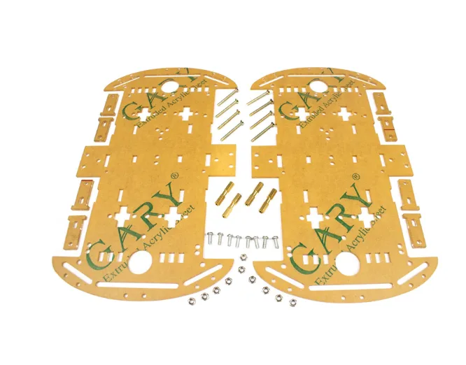
4 Wheels Car Chassis Acrylic Frame
4WD acrylic chassis with flat top deck — perfect for mounting a rigid solar panel while keeping electronics below. Supports panels up to 1.5 kg.
MPPT Charge Controller Integration
A Maximum Power Point Tracking (MPPT) charge controller is essential — a simple PWM controller wastes 10–30% of available solar energy. For robot use, the CN3722 or DFRobot Solar Power Manager Pro are popular choices that handle 4S LiFePO4 charging profiles.
MPPT Wiring
- Connect solar panel + and – to the MPPT’s panel input terminals.
- Connect LiFePO4 battery to MPPT battery terminals (observe polarity).
- Connect load (robot electronics) to MPPT load output — this gives you automatic load disconnect at low battery voltage (typically 10.0V for 4S = 2.5V per cell).
Charging Parameters for 4S LiFePO4
- Charge voltage: 14.4–14.6V (3.60–3.65V per cell)
- Float voltage: 13.6V (3.4V per cell)
- Low voltage cutoff: 10.0V (2.5V per cell)
- Maximum charge current: 0.5C rate recommended for longevity (5A for 10Ah battery)
Battery Management System (BMS)
Even with an MPPT charge controller, a dedicated BMS inside the battery pack is essential for cell balancing and protection:
- Cell balancing: Keeps all 4 cells at the same voltage over hundreds of cycles. Imbalanced cells reduce effective capacity.
- Overcurrent protection: Disconnects the battery if current exceeds the rated maximum (e.g., 30A for a 10Ah pack).
- Short circuit protection: Critical for outdoor robots where wiring faults are more likely.
- Temperature monitoring: Some BMS units include NTC thermistors that disconnect charging below 0°C (LiFePO4 cannot be charged when frozen).
For a 4S 10Ah pack, choose a BMS rated 20–30A continuous discharge. Popular options: Daly 4S 30A, JK BMS 4S (with active balancing).
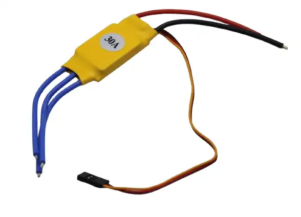
30A BLDC ESC Brushless Electronic Speed Controller
30A ESC rated for brushless motors — compatible with 3S/4S LiFePO4 voltage range. Ideal for larger solar-powered robot drive systems.
Power Distribution Architecture
A well-designed power distribution system prevents the most common failure modes in solar robots:
Recommended Architecture
Solar Panel (18V)
    ↓ MPPT Controller
LiFePO4 Battery (12.8V)
    ↓ Main fuse (20A)
    ├── Motor Driver (12.8V direct)
    ├── Buck 5V/3A → Raspberry Pi / ESP32
    ├── Buck 5V/2A → Cameras / USB devices
└── Buck 3.3V/500mA → Sensors- Always use a main fuse between battery and distribution — 20A for small robots, 40A for larger ones.
- Separate motor power from logic power — motors cause voltage spikes that reset microcontrollers.
- Add large electrolytic capacitors (470–1000µF, 25V) across motor driver power inputs to absorb spikes.
- Use an INA219 current sensor on the main rail to log power consumption data to your microcontroller.

12 Value Assorted Electrolytic Capacitor Kit (Pack of 120)
Assorted electrolytic capacitors — essential for decoupling motor power rails and protecting sensitive electronics in your solar robot.
Chassis and Panel Mounting
The mechanical design of a solar robot must accommodate a large, flat panel while keeping the centre of gravity low:
- Build an elevated panel frame from aluminium extrusion (20×20 T-slot) mounted at the four corners of the chassis. This keeps the panel 10–15 cm above the main body for airflow cooling of electronics.
- Angle the panel slightly forward (5–10°) to improve frontal clearance when the robot drives uphill.
- If using a flexible panel, adhere it directly to a carbon fibre or aluminium sheet, then mount the sheet to the frame. Avoid adhering directly to electronics enclosures — heat build-up degrades both panel and electronics.
- Route solar panel cables through the frame tubes for protection against snagging on vegetation.
Autonomous Power Management Code
An intelligent solar robot should manage its own power budget — slowing down or entering a low-power sleep mode when the battery is low:
// INA219 current sensor on main rail
#include <Adafruit_INA219.h>
Adafruit_INA219 ina219;

void powerManagement() {
  float busVoltage = ina219.getBusVoltage_V();
  float current_mA = ina219.getCurrent_mA();

  // 4S LiFePO4 voltage thresholds
  if (busVoltage > 13.0) {
    setRobotMode(FULL_POWER); // >3.25V/cell — excellent
  } else if (busVoltage > 11.6) {
    setRobotMode(ECO_MODE);   // >2.9V/cell — reduce speed 50%
  } else if (busVoltage > 11.2) {
    setRobotMode(RETURN_HOME); // low — navigate to charging station
  } else {
    setRobotMode(SLEEP); // critical — stop all non-essential systems
  }
}

void setRobotMode(int mode) {
  switch(mode) {
    case FULL_POWER:  maxSpeed = 255; break;
    case ECO_MODE:    maxSpeed = 128; break;
    case RETURN_HOME: initiateReturnToBase(); break;
    case SLEEP:       enterDeepSleep(); break;
  }
}
Frequently Asked Questions
Q: Can LiFePO4 be charged directly from a solar panel without an MPPT?
Technically yes via a PWM charge controller, but you waste 15–30% of solar energy. MPPT is strongly recommended and pays for itself quickly in improved charging speed and battery longevity.
Q: How long will the LiFePO4 battery power the robot overnight (no sun)?
A 4S 10Ah (128Wh) pack powering a 40W robot gives 3.2 hours. Size your battery for your longest expected dark period — for overnight operation, use a 20–30Ah pack.
Q: Can I mix LiFePO4 with a LiPo for a hybrid system?
Not directly — they have different voltage profiles and cannot share a BMS or charger. Use LiFePO4 for the main storage and, if you need high-burst current, add a supercapacitor bank in parallel rather than a separate LiPo pack.
Q: What’s the best MPPT controller size for a 50W panel?
For a 50W panel into a 12.8V LiFePO4, choose an MPPT rated at least 5A output (50W / 12.8V ≈ 3.9A, with 25% margin). A 10A MPPT (CN3722 or Renogy 10A) gives plenty of headroom for future panel expansion.
Q: Are flexible solar panels worth it for robots?
For weight-critical aerial robots or drones, yes. For ground robots, rigid monocrystalline panels are more efficient, cheaper per watt, and more durable against vibration and debris impact.
Get robot chassis, motor drivers, ESCs, capacitors, and more at Zbotic — pan-India delivery. Shop Robotics & DIY at Zbotic and start your solar-powered project.


Add comment