
Table of Contents
- Why L298N with Raspberry Pi?
- Hardware Requirements
- Wiring Diagram: Pi to L298N to Motor
- GPIO and Python Setup
- Basic Direction Control Code
- PWM Speed Control
- Controlling Two Motors (Robot Chassis)
- Using L298N with Stepper Motors on Pi
- Troubleshooting
- Frequently Asked Questions
The Raspberry Pi is a powerful single-board computer, but its GPIO pins can only source about 16 mA per pin — nowhere near enough to drive a DC motor or stepper directly. The L298N dual H-bridge module bridges this gap: it takes low-current logic signals from the Pi and switches high-current motor power independently, letting you drive motors up to 2A per channel at voltages from 5V to 35V.
This guide covers everything from wiring to a complete Python library — including PWM speed control, two-motor robot chassis code, and stepper motor sequences — using RPi.GPIO, the library available on every Raspberry Pi OS installation.
Why L298N with Raspberry Pi?
The L298N module is the go-to motor driver for Pi projects for several practical reasons:
- No additional libraries: Works with standard RPi.GPIO and software PWM
- Dual channel: Controls two DC motors independently, or one bipolar stepper motor
- On-board 5V regulator: When powered by 7–12V, the module’s 5V output can power the Pi itself (for battery-powered robots)
- Wide voltage range: Motor supply from 5V to 35V, logic supply 5V
- Screw terminals: No soldering required for motor and power connections
The main limitation of L298N vs newer drivers (TB6612FNG, DRV8833) is efficiency: the L298N uses bipolar transistors that drop about 2V across each H-bridge, so a 12V supply delivers about 10V effective to the motor. For most hobby robots and projects, this is acceptable.
Hardware Requirements
- Raspberry Pi (any model — Pi 3B+, Pi 4, Pi Zero W all work)
- L298N motor driver module
- DC motor (or two motors for a chassis)
- Power supply: 9–12V for motors (a 2S/3S LiPo or wall adapter), separate 5V for Pi if not using L298N’s regulator
- Jumper wires (female-to-female for Pi GPIO headers)
- Optional: 100 µF capacitor across motor power terminals
Wiring Diagram: Pi to L298N to Motor
L298N Module Terminals Explained
| L298N Terminal | Function | Connect To |
|---|---|---|
| 12V IN | Motor supply positive | 9–12V supply positive |
| GND | Common ground | Supply negative + Pi GND |
| 5V OUT | Regulated 5V output | Optional: Pi 5V pin (if supply ≤12V, keep 12V jumper in place) |
| ENA | Enable Motor A (PWM speed) | Pi GPIO (e.g., GPIO12) |
| IN1 | Motor A direction bit 1 | Pi GPIO (e.g., GPIO20) |
| IN2 | Motor A direction bit 2 | Pi GPIO (e.g., GPIO21) |
| OUT1, OUT2 | Motor A output | Motor A terminals |
| ENB | Enable Motor B (PWM speed) | Pi GPIO (e.g., GPIO13) |
| IN3 | Motor B direction bit 1 | Pi GPIO (e.g., GPIO19) |
| IN4 | Motor B direction bit 2 | Pi GPIO (e.g., GPIO26) |
| OUT3, OUT4 | Motor B output | Motor B terminals |
Important: Always connect Pi GND to the L298N GND terminal. Without a common ground, the logic signals from the Pi float relative to the driver’s reference and control becomes unreliable. Never connect Pi GND to the motor supply negative only — run a wire from L298N GND back to Pi GND directly.
ENA/ENB jumpers: The L298N module ships with jumpers shorting ENA and ENB to 5V (always enabled at full speed). Remove these jumpers and connect ENA/ENB to Pi GPIO pins to enable PWM speed control. Leave them jumpered if you only need on/off motor control.
GPIO and Python Setup
Install / Update RPi.GPIO
On Raspberry Pi OS (Bullseye or Bookworm), RPi.GPIO is pre-installed. Update it:
sudo apt update
sudo apt install python3-rpi.gpio
On Pi 5 running Bookworm, use gpiozero or lgpio instead — RPi.GPIO does not support Pi 5’s new GPIO chip. The code examples below work with RPi.GPIO (Pi Zero through Pi 4).
GPIO Numbering
This guide uses BCM (Broadcom) pin numbering — the number printed next to each pin on a GPIO pinout diagram, not the physical pin number on the header. Set this at the start of every script:
import RPi.GPIO as GPIO
GPIO.setmode(GPIO.BCM)  # Use BCM pin numbers
Basic Direction Control Code
This example controls a single DC motor: forward, backward, stop, and coast (free-spin). The ENA pin is left jumpered (full speed):
import RPi.GPIO as GPIO
import time

# Pin definitions (BCM numbering)
IN1 = 20
IN2 = 21

GPIO.setmode(GPIO.BCM)
GPIO.setwarnings(False)
GPIO.setup(IN1, GPIO.OUT)
GPIO.setup(IN2, GPIO.OUT)

def motor_forward():
    GPIO.output(IN1, GPIO.HIGH)
    GPIO.output(IN2, GPIO.LOW)

def motor_backward():
    GPIO.output(IN1, GPIO.LOW)
    GPIO.output(IN2, GPIO.HIGH)

def motor_stop():     # Active braking (both HIGH)
    GPIO.output(IN1, GPIO.HIGH)
    GPIO.output(IN2, GPIO.HIGH)

def motor_coast():    # Free spin (both LOW)
    GPIO.output(IN1, GPIO.LOW)
    GPIO.output(IN2, GPIO.LOW)

try:
    print("Forward 2 seconds")
    motor_forward()
    time.sleep(2)

    print("Stop")
    motor_stop()
    time.sleep(1)

    print("Backward 2 seconds")
    motor_backward()
    time.sleep(2)

    motor_coast()

finally:
    GPIO.cleanup()
Note on stopping: Setting both IN1 and IN2 HIGH applies active braking (short-circuits the motor back-EMF, causing rapid deceleration). Setting both LOW lets the motor coast to a stop. Use active braking for precision positioning, coast for battery conservation.
PWM Speed Control
Remove the ENA jumper and connect ENA to a GPIO pin to enable speed control via PWM. Software PWM on RPi.GPIO runs at your chosen frequency; 1000 Hz works well for most DC motors:
import RPi.GPIO as GPIO
import time

ENA = 12   # Hardware PWM pin on Pi (GPIO12 = PWM0)
IN1 = 20
IN2 = 21

GPIO.setmode(GPIO.BCM)
GPIO.setwarnings(False)
GPIO.setup(ENA, GPIO.OUT)
GPIO.setup(IN1, GPIO.OUT)
GPIO.setup(IN2, GPIO.OUT)

# Create PWM instance: pin, frequency in Hz
pwm = GPIO.PWM(ENA, 1000)
pwm.start(0)  # Start at 0% duty cycle (stopped)

GPIO.output(IN1, GPIO.HIGH)  # Set direction: forward
GPIO.output(IN2, GPIO.LOW)

try:
    # Ramp up from 0% to 100% speed
    for speed in range(0, 101, 5):
        pwm.ChangeDutyCycle(speed)
        print(f"Speed: {speed}%")
        time.sleep(0.2)

    time.sleep(2)

    # Ramp down
    for speed in range(100, -1, -5):
        pwm.ChangeDutyCycle(speed)
        time.sleep(0.2)

finally:
    pwm.stop()
    GPIO.cleanup()
Hardware PWM vs Software PWM: GPIO12 and GPIO13 on the Pi support hardware PWM (generated by the SoC’s PWM peripheral), which is perfectly smooth. Other GPIO pins use software PWM implemented by a background thread — adequate for motor speed but may stutter slightly under CPU load. For two-motor robots, use GPIO12 for ENA and GPIO13 for ENB to get hardware PWM on both channels.
Controlling Two Motors (Robot Chassis)
Here is a complete robot chassis class controlling left and right drive motors with speed and direction:
import RPi.GPIO as GPIO
import time

class L298NRobot:
    def __init__(self):
        # Motor A (Left)
        self.ENA = 12
        self.IN1 = 20
        self.IN2 = 21
        # Motor B (Right)
        self.ENB = 13
        self.IN3 = 19
        self.IN4 = 26

        GPIO.setmode(GPIO.BCM)
        GPIO.setwarnings(False)
        pins = [self.ENA, self.IN1, self.IN2,
                self.ENB, self.IN3, self.IN4]
        for pin in pins:
            GPIO.setup(pin, GPIO.OUT)

        self.pwm_a = GPIO.PWM(self.ENA, 1000)
        self.pwm_b = GPIO.PWM(self.ENB, 1000)
        self.pwm_a.start(0)
        self.pwm_b.start(0)

    def _set_motor_a(self, speed, forward=True):
        if forward:
            GPIO.output(self.IN1, GPIO.HIGH)
            GPIO.output(self.IN2, GPIO.LOW)
        else:
            GPIO.output(self.IN1, GPIO.LOW)
            GPIO.output(self.IN2, GPIO.HIGH)
        self.pwm_a.ChangeDutyCycle(abs(speed))

    def _set_motor_b(self, speed, forward=True):
        if forward:
            GPIO.output(self.IN3, GPIO.HIGH)
            GPIO.output(self.IN4, GPIO.LOW)
        else:
            GPIO.output(self.IN3, GPIO.LOW)
            GPIO.output(self.IN4, GPIO.HIGH)
        self.pwm_b.ChangeDutyCycle(abs(speed))

    def forward(self, speed=75):
        self._set_motor_a(speed, forward=True)
        self._set_motor_b(speed, forward=True)

    def backward(self, speed=75):
        self._set_motor_a(speed, forward=False)
        self._set_motor_b(speed, forward=False)

    def turn_left(self, speed=60):
        self._set_motor_a(speed, forward=False)  # Left motor back
        self._set_motor_b(speed, forward=True)   # Right motor forward

    def turn_right(self, speed=60):
        self._set_motor_a(speed, forward=True)
        self._set_motor_b(speed, forward=False)

    def stop(self):
        self.pwm_a.ChangeDutyCycle(0)
        self.pwm_b.ChangeDutyCycle(0)

    def cleanup(self):
        self.stop()
        self.pwm_a.stop()
        self.pwm_b.stop()
        GPIO.cleanup()

robot = L298NRobot()
try:
    robot.forward(speed=80)
    time.sleep(2)
    robot.turn_left(speed=65)
    time.sleep(0.8)
    robot.forward(speed=80)
    time.sleep(2)
    robot.stop()
finally:
    robot.cleanup()
Using L298N with Stepper Motors on Pi
The L298N can also drive a 4-wire bipolar stepper motor. Connect Coil A wires to OUT1/OUT2 and Coil B wires to OUT3/OUT4. Remove all ENA/ENB jumpers and connect ENA and ENB both to Pi 3.3V (or 5V) to keep both channels permanently enabled — stepper control uses IN1–IN4 exclusively for sequencing:
import RPi.GPIO as GPIO
import time

IN1, IN2, IN3, IN4 = 20, 21, 19, 26

GPIO.setmode(GPIO.BCM)
for pin in [IN1, IN2, IN3, IN4]:
    GPIO.setup(pin, GPIO.OUT)
    GPIO.output(pin, GPIO.LOW)

# Half-step sequence (8 steps per cycle, smoother motion)
step_sequence = [
    [1,0,0,0],
    [1,1,0,0],
    [0,1,0,0],
    [0,1,1,0],
    [0,0,1,0],
    [0,0,1,1],
    [0,0,0,1],
    [1,0,0,1],
]

def step(steps, delay=0.002, forward=True):
    seq = step_sequence if forward else step_sequence[::-1]
    for _ in range(steps):
        for phase in seq:
            GPIO.output(IN1, phase[0])
            GPIO.output(IN2, phase[1])
            GPIO.output(IN3, phase[2])
            GPIO.output(IN4, phase[3])
            time.sleep(delay)

try:
    step(200, delay=0.002, forward=True)   # ~1 revolution CW
    step(200, delay=0.002, forward=False)  # ~1 revolution CCW
finally:
    for pin in [IN1, IN2, IN3, IN4]:
        GPIO.output(pin, GPIO.LOW)  # De-energise coils
    GPIO.cleanup()
Troubleshooting
Motor does not turn but gets warm
The motor is energised (current flowing) but the enable pin is not toggling, or IN1/IN2 are both HIGH (active brake). Check ENA jumper state — if jumpered and ENA not connected to a Pi GPIO, the channel is permanently enabled. Verify your IN1/IN2 outputs are not both HIGH simultaneously.
Pi freezes when motor starts
The motor’s startup current spike is pulling down the Pi’s 5V supply. Do not use the L298N’s 5V output to power the Pi when the motor supply is under 9V (the regulator needs headroom). Use a separate USB power supply for the Pi, or a quality LiPo + BEC regulator.
PWM speed control does nothing
The ENA/ENB jumper is still in place, hardwiring ENA to 5V (100% duty cycle). Remove the jumper before using PWM on that pin.
GPIO.cleanup() warning at script exit
Always call GPIO.cleanup() in a finally block to reset all GPIO pins to inputs and avoid resource conflicts on the next run. The warning appears if you call setup() on already-configured pins without cleanup.
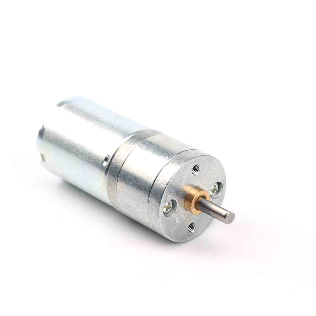
25GA-370 12V 12RPM DC Reducer Gear Motor
A compact 12V gear motor ideal for Raspberry Pi robot chassis projects — built-in reduction for high torque at low speed, perfect for L298N control.
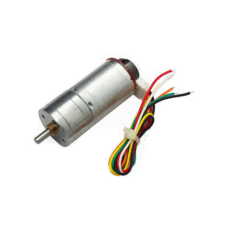
25GA-370 12V 12RPM DC Reducer Gear Motor with Encoder
Same great gear motor but with a quadrature encoder — enables closed-loop position control on Raspberry Pi for accurate distance and speed measurement.
Frequently Asked Questions
Can Raspberry Pi GPIO pins be damaged by L298N signals?
The Pi GPIO pins are 3.3V logic. The L298N’s input pins (IN1–IN4, ENA, ENB) are TTL-compatible and accept 3.3V HIGH as a valid logic high, so no level shifter is needed. However, never connect Pi GPIO directly to the L298N’s output terminals or motor power — those carry high voltage and will immediately destroy the Pi.
What is the maximum motor current the L298N can handle?
The L298N IC is rated at 2A continuous per channel (4A peak) with adequate heatsinking. The module typically includes a small heatsink, but for sustained loads above 1.5A, add a larger heatsink or use a fan. The module will thermally shut down before permanent damage at overload.
Does this code work on Raspberry Pi 5?
Raspberry Pi 5 uses a different GPIO chip (RP1) incompatible with RPi.GPIO. Use gpiozero (which is Pi 5 compatible) or lgpio library instead. The gpiozero library has a built-in Motor class that wraps L298N control elegantly.
How do I control motor speed from a web browser on the Pi?
Use Flask (Python web framework) to create a simple HTTP API that calls the motor functions. Run Flask on the Pi, then send HTTP GET/POST requests from any browser on the same network. The Pi’s IP + port 5000 becomes your robot’s control panel. Add ngrok or a reverse proxy for internet access.
Can I run this without a separate motor power supply?
For very small motors (under 200 mA), you can use the Pi’s 5V GPIO pin as motor supply, connecting it to L298N’s 5V supply terminal (not the 12V terminal). Remove the 12V jumper. The Pi’s 5V rail can source up to 2A (Pi 4) or 3A (Pi 5), shared across all USB devices and GPIO. This is marginal and not recommended for robots, but works for light bench testing.
Ready to Build Your Pi Robot?
Raspberry Pi + L298N is one of the most capable and affordable motor control combinations for hobby robotics. The Python code above gives you a solid foundation — add ultrasonic sensors, a camera module, or a web interface to build increasingly sophisticated autonomous systems. Zbotic stocks gear motors, stepper motors, and all the drivers you need for your Pi motor project.


Add comment